- 18 -
English
SWING APRICODE 230
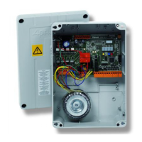
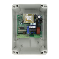
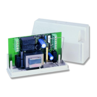
CONTROL UNIT
Plug-in memory module (optional)2.1.1
FIRST installation use Down-load/Up-load
NOT powered Control Unit Powered Control Unit
insert the plug-in Memory Module
power up
carry out
Down-load or Up-load
(par.Programming)
if the
functioning
parameters
have been
saved in
the module
memory
system
START-UP
if the functioning
parameters are
missing on the
module
Init
is shown
on the display
at the end
done is shown on
the display
press the YELLOW
and BLUE for
approx. 3 sec
Lrn; carry out
the self-teaching
disconnect power,
then power up again
the displays switch off: the system is ready to work
Electric system set-up2.2
Before you install components you should prepare the
electrical connections of the control and safety devices in
the system. Follow the instructions given on the “
Electrical
equipment setup diagram
” in the instruction manual supplied
with the operator. Follow the instructions given in this manual
and the instructions given on components already installed.
Warning
!
The system must only be installed by skilled personnel
qualifi ed in compliance with the regulations of the country
of installation (CEI 64 - 8 / EN 60335-1 standards).
Electrical connections2.3
Check that all the connections are as specifi ed in the
Layout
diagram
below. Check that the cables are connected to the correct
inputs. Check that the minimum cable section is as specifi ed.
Warning
!
Switch OFF the mains power supply before you start
connecting up.
Before you connect up the product and accessories, check
them for damage.
IMPORTANT! Read and follow the instructions for all the
components installed.
Faulty connections can cause equipment operating faults
and may seriously damage the equipment. Failure to
connect up the equipment correctly will void your guarantee.
Do NOT use intercom or telephone cable.
IMPORTANT: Complete all connections and checks before
you connect up to the 230 V AC mains power supply.
The equipment must be earthed. Connect the earth to the
earth terminals.
Connecting up to the mains power supply2.4
POWER SUPPLY - 230 V AC monophase 50 Hz.
●
Use a power supply cable with 3 wires and a minimum
section of 1.5 mm
2
; the cable must comply with current
electrical regulations. Choose the section of the cable to
match the length of the line.
IMPORTANT ! Always install, upstream of the line, a mains
switch which guarantees a multipole cut-off with minimum
contact opening of 3 mm (connect it to a 6 A differential
overload switch with sensitivity of 30 mA).
J1 RS232 / Urmet interface serial connector
J4 13-pin removable terminal board - connections for
control and accessory inputs
1-2 Electric lock - 12 V AC output with maximum
connectable load of 15 W controlling the electric lock
for approx. 1.5 seconds in the opening stage.
3-4 Flashing LED, 24 V DC - two-wire cables with
min. section 1 mm
2
. DO NOT use other types of
fl ashing light.
5-4 Warning light/AUX output - 24 V DC output with
maximum load of 3 W for gate status warning light.
6-10 Pedestrian opening start (N/O).
7-10 24 V power supply for ACCESSORIES.
8-10 Auxiliary safety devices (photocell, safety edge)
(N.C. safety contact).
9-10 Closing photocell input (N.C. safety contact)
11-12 STOP (N/C safety contact) to stop wing.
13-12 START (N/O) starts wing opening and closing.
J9
J10
Plug-in terminal boards - set up with connections to
motor encoder (not used)
J12 Plug-in memory module connector (
OPTIONAL
)
J13 Motor 1 capacitor connection terminal board
J14 Motor 2 capacitor connection terminal board
J15 Removable terminal board
-
power for two 24 V DC
motor outputs - 3-wire cables with minimum section
of 1.5 mm
2
+ earth
J16 Removable terminal board - safety edge and
photocell test input
M1 Removable terminal board - 230 V AC phase-
neutral-earth connection
JRX Connector for built-in receiver (CAUTION This
connector can only be plugged in one way. Ensure
that the plug-in direction is correct. Do not force).
CN1 10-pin connector for RPL-ECO receiver (alternative
to built-in receiver)
CN2 3-pin Aprimatic connector for accessories;
connection for radio card compatible with UNICO
receiver (alternative to built-in receiver) - Access
control decoder
CN3 Terminal board for built-in receiver antenna
FS1
FS2
Transformer (230 V AC) primary faston contacts
FS3
FS4
FS5
Transformer (9-0-9 VAC) secondary faston contacts
FS6
FS7
Transformer (12 V AC) secondary faston contacts
F1 Mains power supply and 230 V motor power supply
fuse
F2 Electric lock fuse
F3 External accessories protection fuse (24 V DC)
DL1 Power supply ON and FIRMWARE LED
DS1
DS2
DS3
DS4
LED display - parameters and values
Card componentstab. 2 -
 Loading...