Appendices 83
Appendix E: Cable Pinout Information
NOTE: Only the DSR1024, DSR2035 and DSR8035 switches have the 8-pin modular jack for the modem and
console/setup ports. All other models have the 9-pin D-shell connectors for these ports.
1
8
45
2
3
6
7
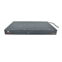
Figure E.1: Modem Jack
Table E.1: Descriptions for Figure E.1
Pin Number Description Pin Number Description
1 Request to Send (RTS) 5 Transmit Data (TXD)
2 Data Set Ready (DSR) 6 Signal Ground (SG)
3 Data Carrier Detect (DCD) 7 Data Terminal Ready (DTR)
4 Receive Data (RXD) 8 Clear to Send (CTS)
1
8
45
2
367
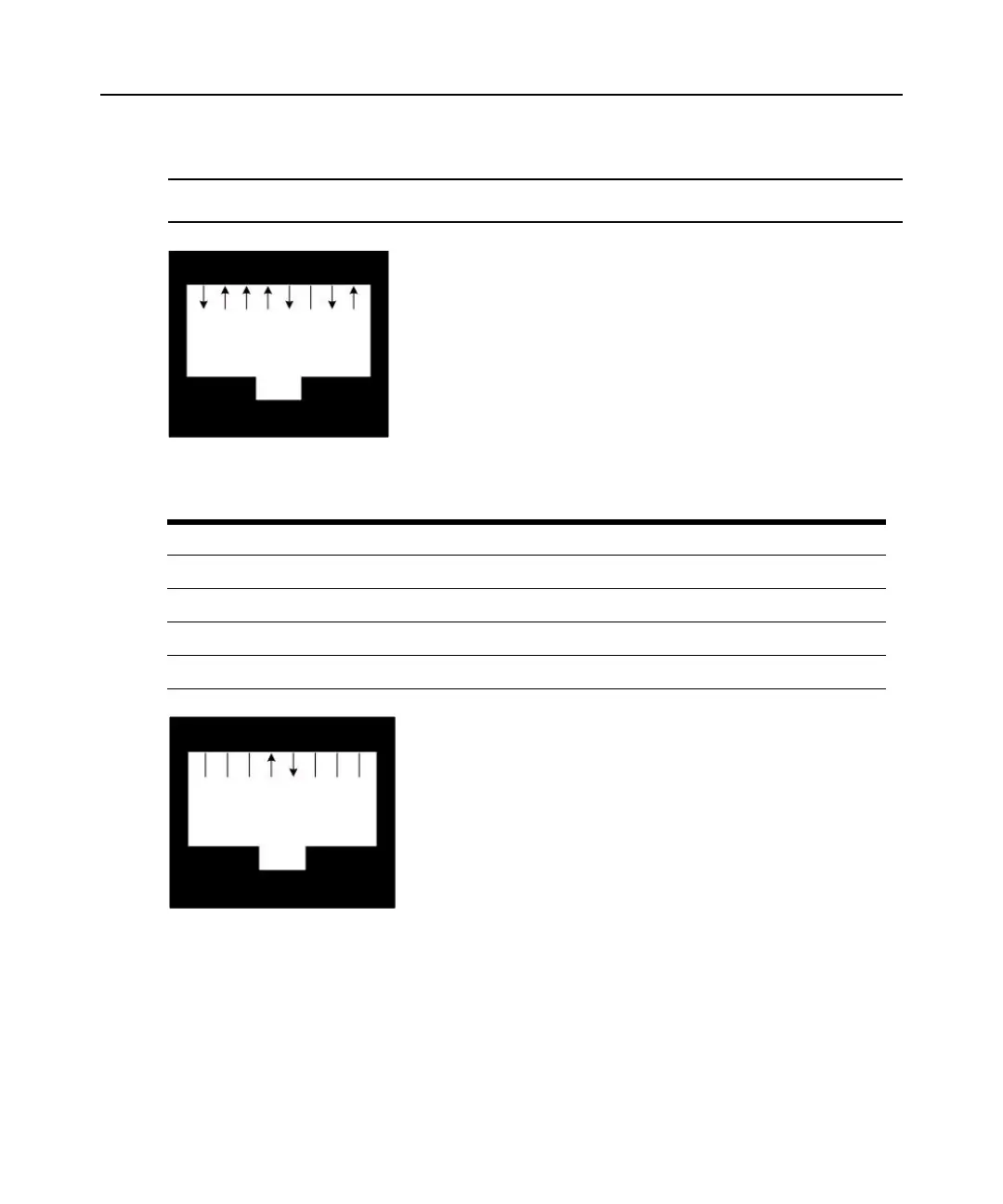
Figure E.2: Console/Setup Jack
 Loading...