Azbil Corporation Installation
MagneW FLEX+/PLUS+ Electromagnetic Flowmeter Detector 2-49
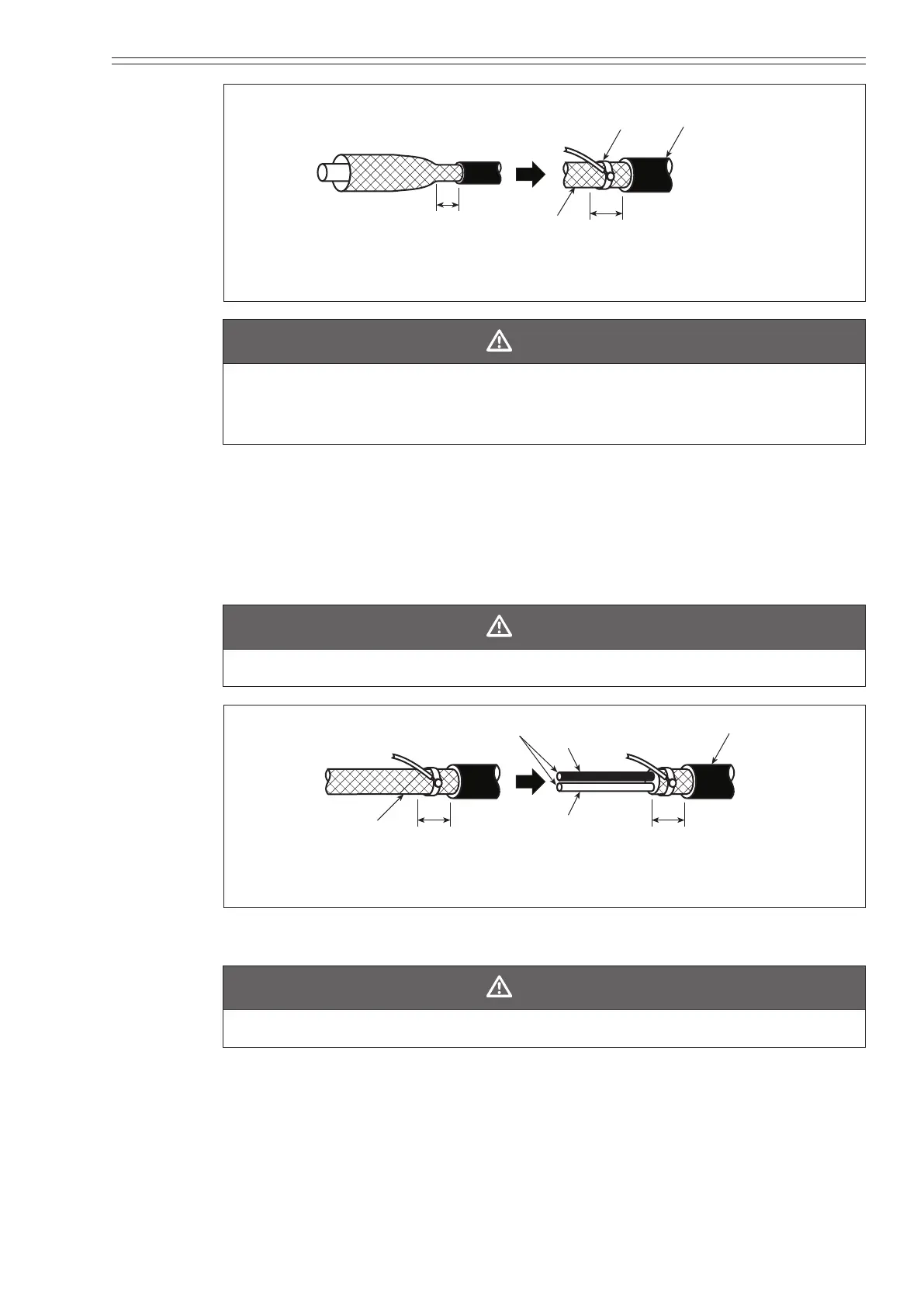
5 mm
Attach the lead wire
to the middle of this
Outside
shield
C-wire
Lead wire
sheath
5 mm
(0.2 inch)
Figure 2-40 Attaching the C-wire
CAUTION
Be sure to use adequate solder so that contact failure will not occur between the
C-wire and the outside shield. If the soldering connection is insecure, noise is
generated due to contact resistance.
~Note
If the outside shield is not allowed to bend during soldering, in some
cases, the conductive tube cannot be peeled o due to the heat of the
solder.
(4) Cut the outside shield o at a point 5 mm (0.2 inch) from the outside sheath,
leaving the specied length from the end of the outside shield.
CAUTION
Do not cut into the inside sheath.
5 mm
Outside
shield
C-wire
5 mm
White
C-wire
Black
Inside sheath
Figure 2-41 Trimming the outside shield
(5) Peel o the inside sheath so that a 15 mm (0.59 inch) section remains.
CAUTION
Do not cut into the inside shield.
~Note
Check the operating manual for the product you are using to
determine whether the lead wires (SA and SB) are necessary. If not,
skip to Step 8.

 Loading...