R5905752 /16 DP2K C146
Convergence test pattern
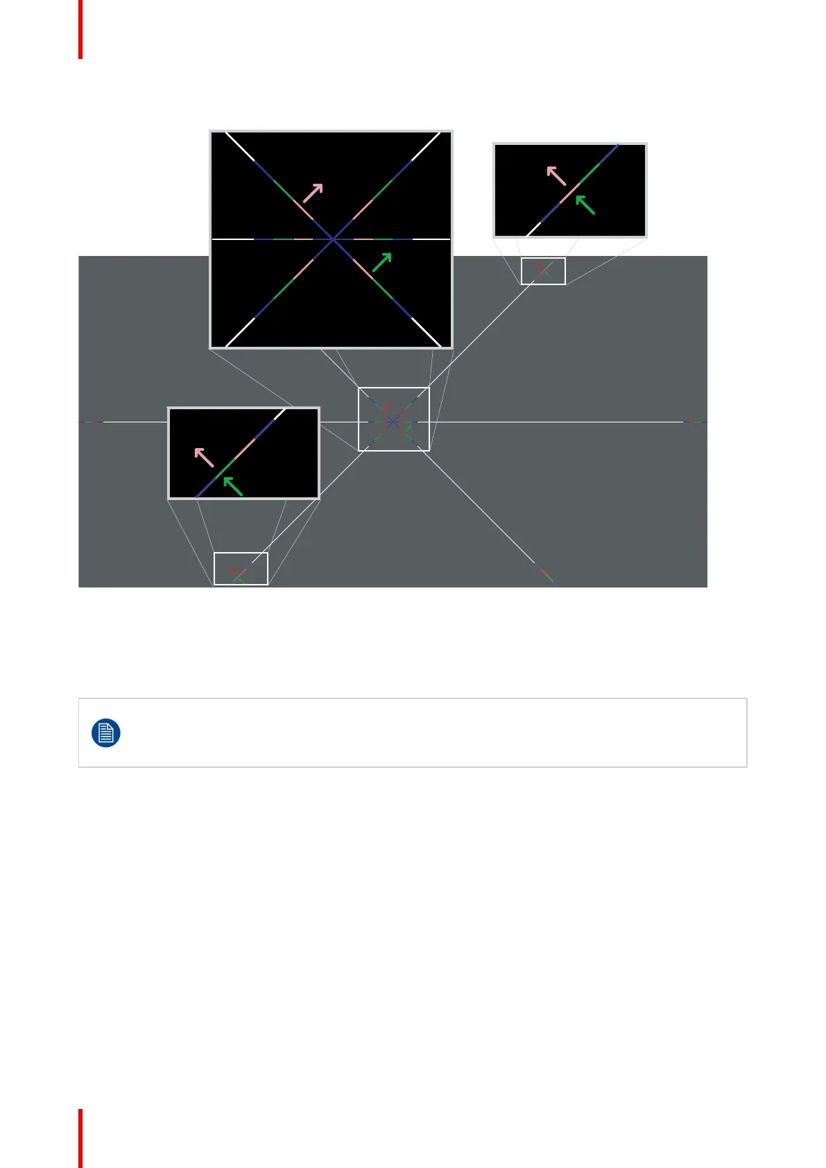
Image 12–3 Convergence test pattern
The test pattern illustrated above is specially designed for convergence purposes. The test pattern has three
red arrows numbered from 1 to 3 and three green arrows numbered from 4 to 6. These numbers and colors
correspond with the numbers and colors of the extended control knobs. The direction of the arrow shows the
movement of the channel color (red or green) when turning the corresponding knob in the direction indicated
by the arrow marked on the knob.
The three convergence control knobs of one channel stand in relation with each other. So, a change
to one of them will also effect the adjustment results of the two others. Therefore, all three control
knobs have to be alternately and repeatedly adjusted until the projected color is perfectly converged
with the blue reference color of the test pattern.
Adjustment range
• The adjustment range is limited to approximately 30 pixels in both directions.
• One turn (360°) of a control knob relates to an approximately 30 pixel displacement on the screen.
• When changing the adjustment direction there will be some play of approximately one turn (360°).
12.2 Preparing the convergence adjustment
Required tools
Flat blade screwdriver
Prepare projector for convergence adjustment
1. Remove all side covers and top cover of the projector, see “Removal and installation of projector covers”,
page 123.
2. Open the sealed compartment of the light processor, see “Open the sealed compartment”, page 129.
Convergence
 Loading...


