35R5905752 /16 DP2K C
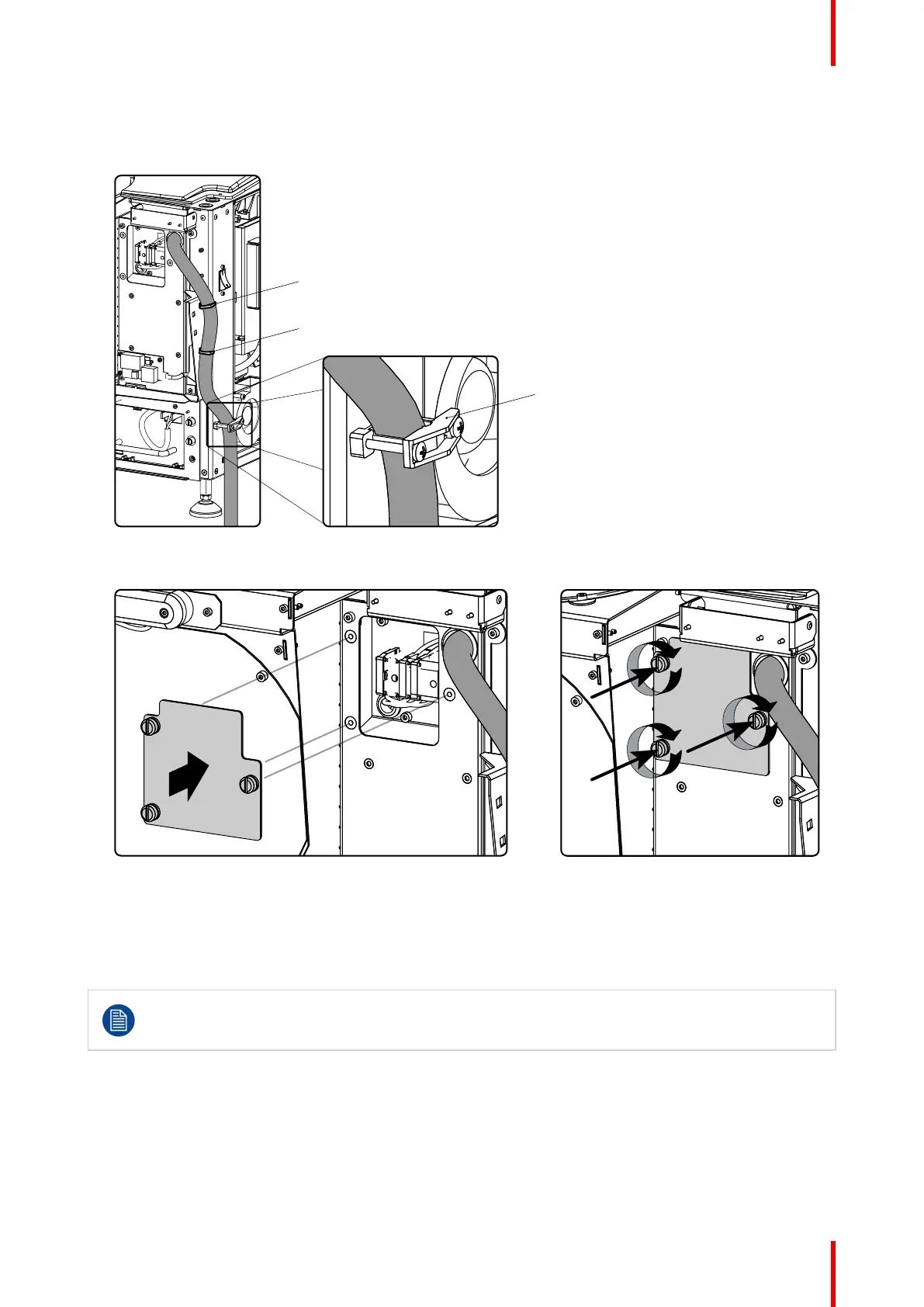
Use the appropriate screws, depending on the diameter of the cable (two sets of screws are delivered with
the projector in a separate bag). Turn in both screws so that the end of the screws are far enough in the
plastic part and that the feet of that part grip in the chassis. Check the fixation by pulling on the gland.
Image 3–8
5. Reinstall the cover of the main AC compartment.
Image 3–9
6. Reinstall the rear cover and lamp cover of the projector.
3.4 Power loop through to the projector electronics
This procedure explains how to provide the projector electronics with power in case no UPS unit is
used. Note that the projector is by default configured for use without UPS. So, the short power link
cable is already installed.
INLET/OUTLET fixation accessories
The plugs of the power cable which are inserted in the power INLET or OUTLET socket of the projector have
to be secured. The projector is equipped with fixation accessories as illustrated below.
Physical installation
 Loading...


