Commissioning
Index (hex) Name Meaning
MDP 407 Profile DS402 Profile
8010:12 [}166] 2002:12 [}147]
Current loop integral time is calculated according to the symmetrical optimum
8010:13 [}166] 2002:13 [}147]
Current loop proportional gain is calculated according to the symmetrical optimum
8011:11 [}168] 2003:11 [}148]
Max. current is adopted directly from the electronic type plate of the
connected motor
8011:12 [}168] 2003:12 [}148]
Rated current is adopted directly from the electronic type plate of the
connected motor
8011:13 [}168] 2003:13 [}148]
Motor pole pairs is adopted directly from the electronic type plate of the
connected motor
8011:15 [}168] 2003:15 [}148]
Commutation offset is always set to -90°
8011:16 [}168] 2003:16 [}148]
Torque constant is adopted directly from the electronic type plate of the
connected motor
8011:18 [}168] 2003:18 [}148]
Rotor moment of inertia is adopted directly from the electronic type plate of the
connected motor
8011:19 [}168] 2003:19 [}148]
Winding inductance is adopted directly from the electronic type plate of the
connected motor
8011:1B [}168] 2003:1B [}148]
Motor speed limitation Calculation of the max. speed of the connected motor
8011:2B [}168] 2003:2B [}148]
Motor temperature warn level is adopted directly from the electronic type plate of the
connected motor
8011:2C [}168] 2003:2C [}148]
Motor temperature error level is adopted directly from the electronic type plate of the
connected motor
8011:2D [}168] 2003:2D [}148]
Motor thermal time constant is adopted directly from the electronic type plate of the
connected motor
8012:11 [}169] 2004:11 [}149]
Release delay is adopted directly from the electronic type plate of the
connected motor
8012:12 [}169] 2004:12 [}149]
Application delay is adopted directly from the electronic type plate of the
connected motor
8012:14 [}169] 2004:14 [}149]
Brake moment of inertia is adopted directly from the electronic type plate of the
connected motor
Also see about this
2 EL72x1-0010-MDP742 - Object description and parameterization [}165]
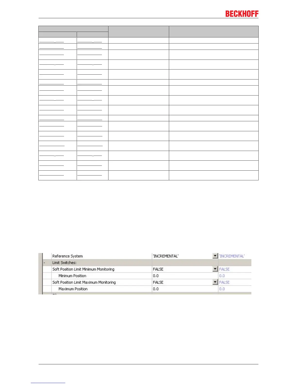
6.2.8 Configuring the limit switch
Software end position monitoring
The TwinCAT NC can be used to set software end position monitoring for the EL72x1-0010 to ensure the
safety of the system. The axis does not move beyond the set position (maximum/minimum end position).
End position monitoring can be activated in the Parameter tab for the corresponding axis.
Fig.142: Pull-down menu for activating end position monitoring
Limit switch
It is not possible to connect a limit switch directly to the terminal for direct evaluation. Alternatively, the limit
switch can be read via a digital input terminal, or the software end position monitoring can be used.
EL72x1-0010114 Version: 2.0

 Loading...
