Installation
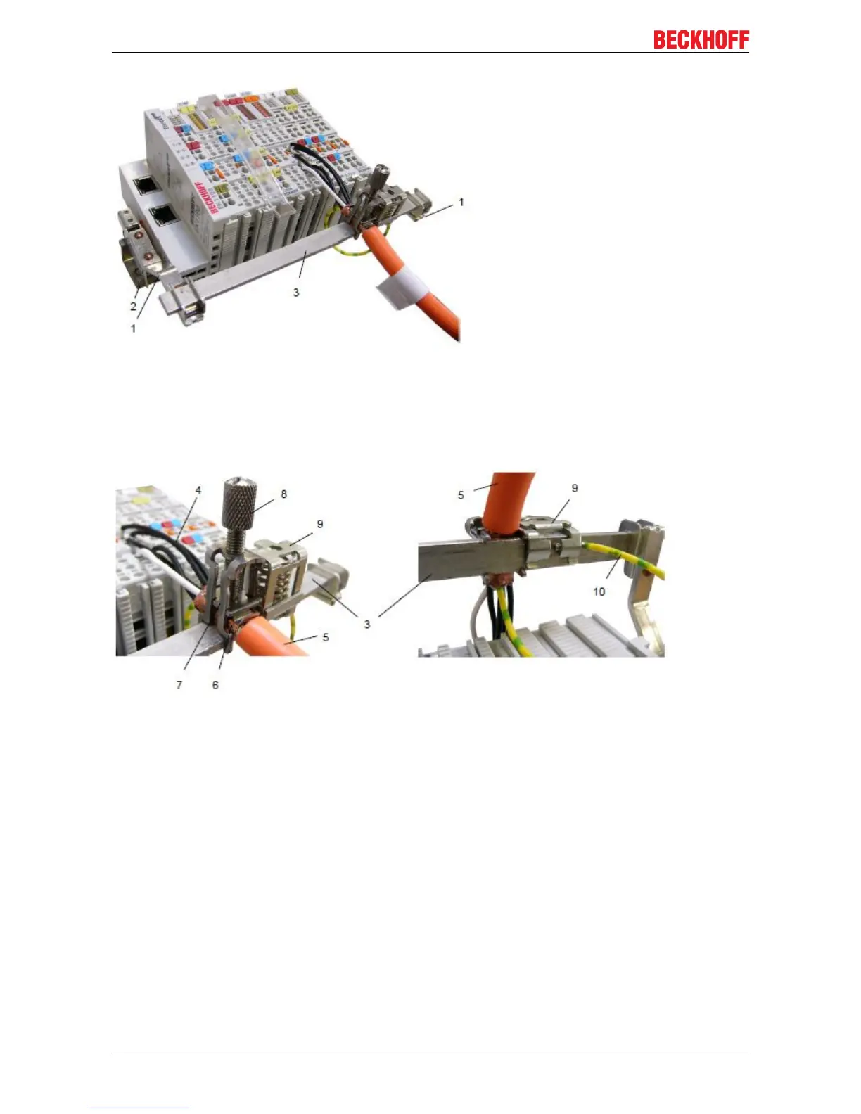
Fig.30: Shield busbar
Connect the cores 4 of the motor cable 5, then attach the copper-sheathed end 6 of the motor cable 5 with
the shield clamp 7 to the shield busbar 3. Tighten the screw 8 to the stop.
Fasten the PE clamp 9 to the shield busbar 3. Clamp the PE core 10 of the motor cable 5 under the PE
clamp 9.
Fig.31: Shield connection
Connection of the feedback cable
The shield of the feedback cable is connected via the metallic plug fastener when screwing the feedback
plug onto the AM3100.
On the terminal side the shield can also be connected.. Connect the cores of the feedback cable and attach
the copper-sheathed end of the feedback cable to the shield busbar 3 with the shield clamp 7. The motor
cable and the feedback cable can be connected to the shield clamp 7 with the screw 8.
5.7 Notes on current measurements using Hall sensors
The device described in this documentation features one or several integrated Hall sensor for the purpose of
current measurements.
During this process, the Hall sensor monitors the magnetic field generated by a current flowing through a
conductor.
In order to prevent compromising the measurement we recommend screening exterior magnetic fields from
the device, or to keep such fields at an adequate distance.
EL72x1-001038 Version: 2.0

 Loading...
