Basics communication
4 Basics communication
4.1 EtherCAT basics
Please refer to the chapter EtherCAT System Documentation for the EtherCAT fieldbus basics.
4.2 EtherCAT cabling – wire-bound
The cable length between two EtherCAT devices must not exceed 100 m. This results from the FastEthernet
technology, which, above all for reasons of signal attenuation over the length of the cable, allows a maximum
link length of 5 + 90 + 5 m if cables with appropriate properties are used. See also the Design
recommendations for the infrastructure for EtherCAT/Ethernet.
Cables and connectors
For connecting EtherCAT devices only Ethernet connections (cables + plugs) that meet the requirements of
at least category 5 (CAt5) according to EN 50173 or ISO/IEC 11801 should be used. EtherCAT uses 4 wires
for signal transfer.
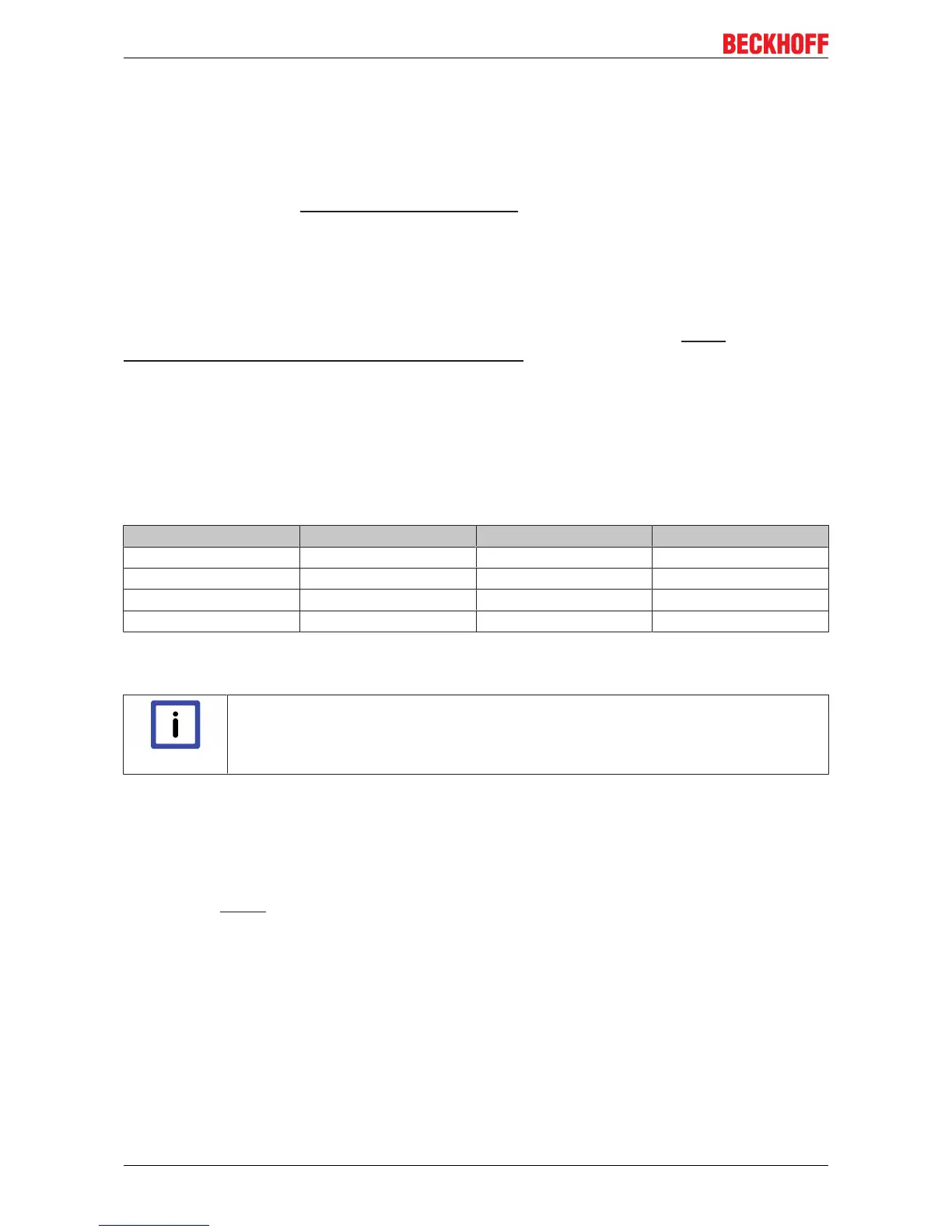
EtherCAT uses RJ45 plug connectors, for example. The pin assignment is compatible with the Ethernet
standard (ISO/IEC 8802-3).
Pin Color of conductor Signal Description
1 yellow TD + Transmission Data +
2 orange TD - Transmission Data -
3 white RD + Receiver Data +
6 blue RD - Receiver Data -
Due to automatic cable detection (auto-crossing) symmetric (1:1) or cross-over cables can be used between
EtherCAT devices from Beckhoff.
Note
Recommended cables
Suitable cables for the connection of EtherCAT devices can be found on the Beckhoff web-
site!
E-Bus supply
A bus coupler can supply the EL terminals added to it with the E-bus system voltage of 5 V; a coupler is
thereby loadable up to 2A as a rule (see details in respective device documentation).
Information on how much current each EL terminal requires from the E-bus supply is available online and in
the catalogue. If the added terminals require more current than the coupler can supply, then power feed
terminals (e.g. EL9410) must be inserted at appropriate places in the terminal strand.
The pre-calculated theoretical maximum E-bus current is displayed in the TwinCAT System Manager. A
shortfall is marked by a negative total amount and an exclamation mark; a power feed terminal is to be
placed before such a position.
EL72x1-001018 Version: 2.0

 Loading...
