23
F
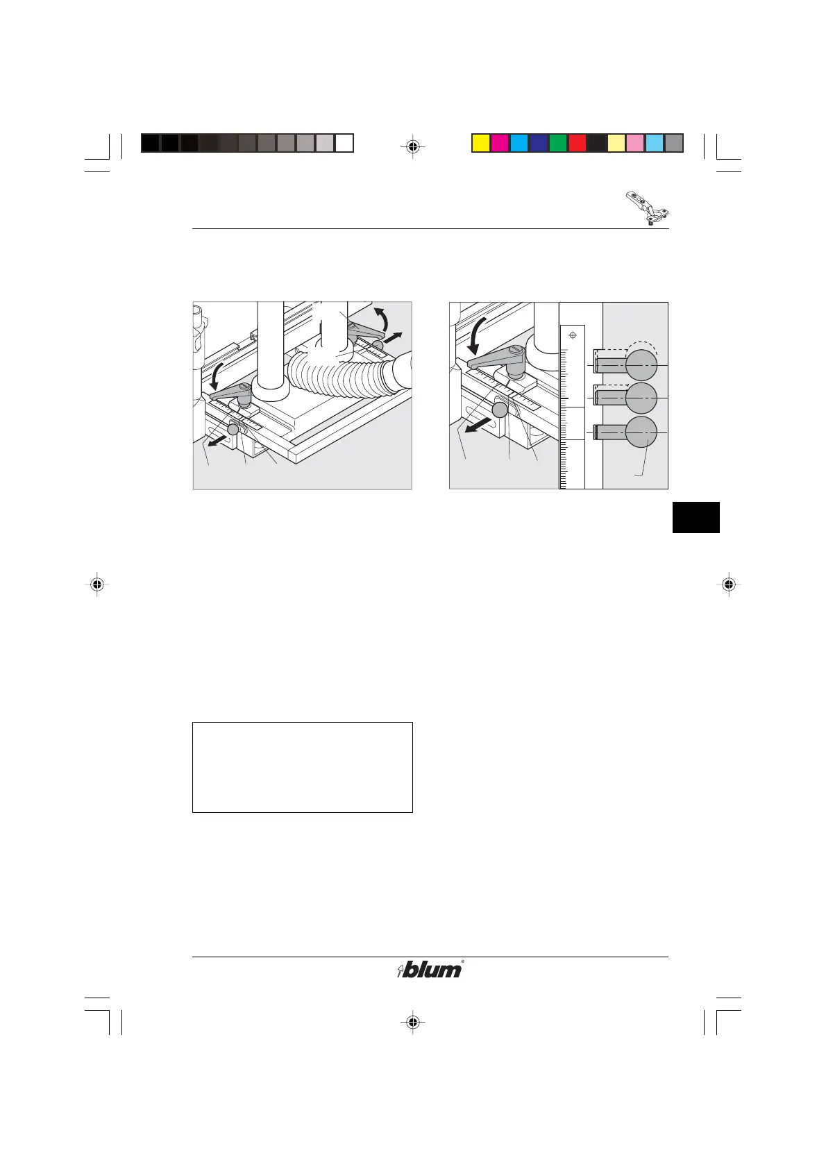
Drilling of hinge pattern
!
F15
F16
SY MB DP
SY
MB
DP
0
10
20
30
40
50
SY
MB
DP
F16
Pos.
1/2
Pos.
3/4
Pos.
5
11. Fencing System (D4) adjustments
• Always place operation mode switch
to set up position and disconnect the
machine from it’s electrical source
(unplugged) before performing any
work on the drill heads, fences,
stops, or pneumatic break.
• Release both clamping levers (F15).
• Pull out the fixing pins (F16) on both
sides and set the stop system (D4)
to MB.
Note:
The fencing system includes
5 fixing positions.
(see point 12 )
• Tighten the clamping levers (F15) on
both sides.
12. Fixed positions of the stop system
• Always place operation mode switch
to set up position and disconnect the
machine from it’s electrical source
(unplugged) before performing any
work on the drill heads, fences,
stops, or pneumatic break.
Pos. 1 = 5 mm (3/16“)
Lock the fixing bolts (F16) into place
and pull the stop system forward.
Pos. 2 = 9 mm (3/8“)
Lock the fixing bolts (F16) into place
and push the stop system backward.
Pos. 3 = 20 mm (13/16“)
Lock the fixing bolts (F16) into place
and pull the stop system forward.
Setting: ‘DP’
Pos. 4 = 23.5 mm (15/16“)
Lock the fixing bolts (F16) into place
and push the stop system backward.
Setting: ‘MB’
Pos. 5 = 37 mm (1-7/16“)
Lock the fixing bolts (F16) into place.
Setting: ‘SY’
%$0,1,35(66)$,G1US $0
 Loading...