29
G
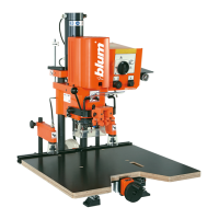
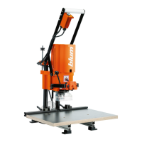
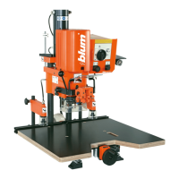
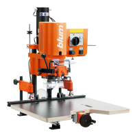
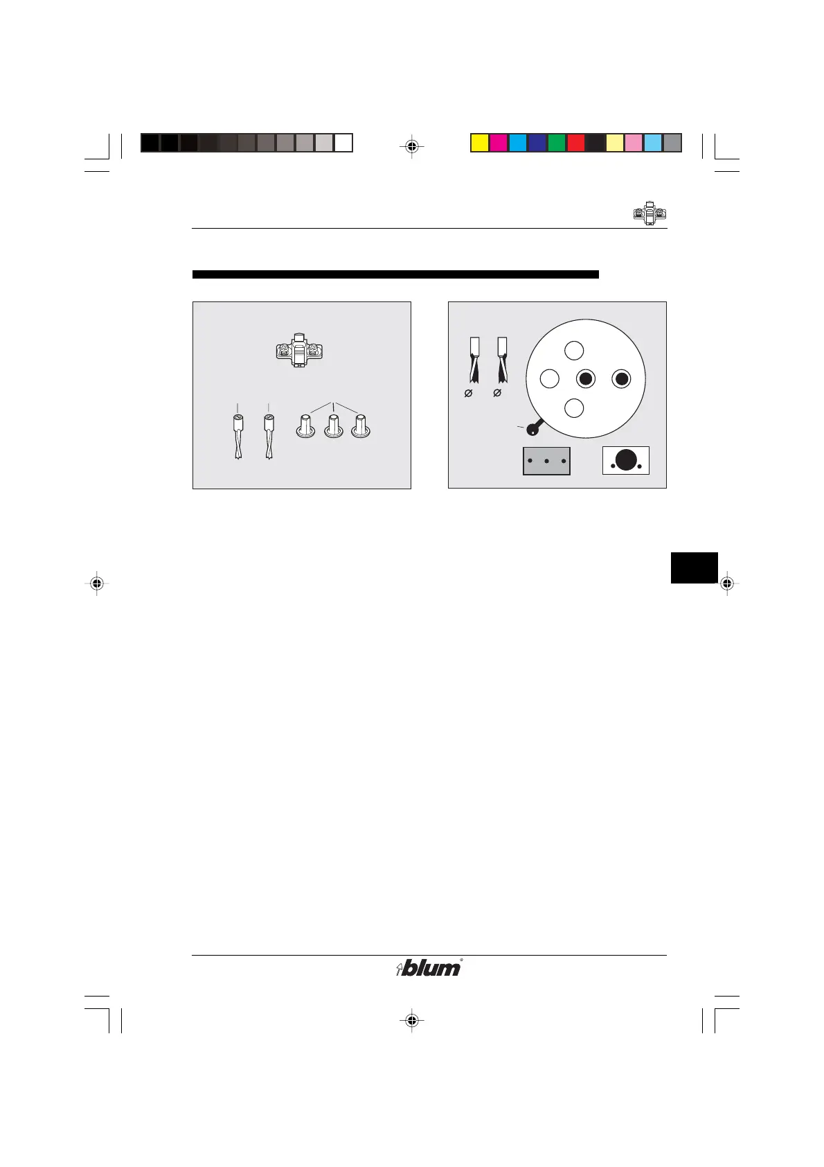
Installation of wing mounting plates
G1G2
F3
G
1
5
F
3
G
3
F
6
G
2
F
3
F
3
G
1
G
2
5
Installation of wing mounting plates with system screws
1. Necessary parts
• Drill bits:
- one 5 mm dia. rotating clock wise
(G1) (marked black)
- one 5 mm dia. rotating counter
clockwise (G2) (marked orange)
• Three cover caps (F3)
• Cabinet side panel
• Mounting plates with system screws
2. Drill-bit length
(see section F- point 2)
3. Change drill pattern
• Pull out fixing pin (F5) on drill head.
• At the same time, move lever (F6)
to Symbol for line boring pattern
(G3).
• Make sure, fixing pin snaps back to
lock gearbox position.
4. Install drill bits
(see section F- point 4)
5. Check drilling depth adjustment
(see section F - points 5/6/7)
6. Check pneumatic brake setting
(see section F -point 8/9/10)
%$0,1,35(66)$,G1US $0
 Loading...