Access Easy Controller 2.1 4-Reader Board | en 25
Robert Bosch (SEA) Pte Ltd Hardware Installation Manual 2018.11 | 1.0.6 | F.01U.122.796
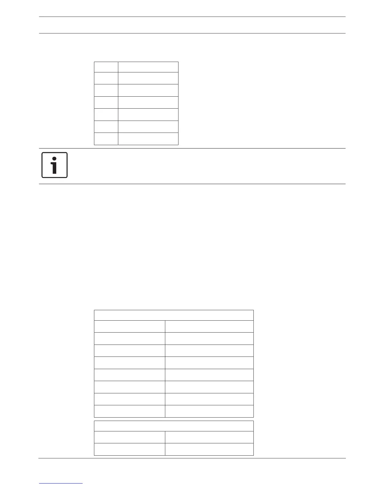
The pin configured for each reader connector is shown in the table below.
Pin# Function
1 12 VDC
2 Ground
3 Data 0
4 Data 1
5 Green LED Control
6 Buzz Control
Notice!
Each connector is able to provide a maximum current of 150mA at 12 VDC. This is sufficient
power for most readers. Readers requiring higher current will need to have the power
supplied from an external power supply.
6.1.3 Input Connectors
Two 8-pin terminal strips across the top of the 4-Reader board provide termination points for
the door contacts and request-to-exit devices associated with the readers. The terminal strips
are identified as T6 and T7 on the 4-Reader board.
For each of the four readers this board can control, there are two terminals each for
connection of a door contact and a request-to-exit device. Both circuits (contact and REX) are
supervised and should be terminated according to the type of supervision applied to that
particular input (Wiring Diagram for Supervised Inputs, page 57). If either contact or REX
device are not to be used, then the termination resistor should be installed across the
terminals within the controller. Refer to How to Install Reader and Field Devices, page 47, for
detailed wiring diagrams.
The tables below show the various termination points on the terminal strips.
T6 Terminal Strip
IN1 Request-to-exit for reader #1
GND Request-to-exit for reader #1
IN2 Door contact for reader #1
GND Door contact for reader #1
IN3 Request-to-exit for reader #2
GND Request-to-exit for reader #2
IN4 Door contact for reader #2
GND Door contact for reader #2
T7 Terminal Strip
IN5 Request-to-exit for reader #3
GND Request-to-exit for reader #3

 Loading...