36 en | 8-Input-Output Board Access Easy Controller 2.1
2018.11 | 1.0.6 | F.01U.122.796 Hardware Installation Manual Robert Bosch (SEA) Pte Ltd
T4 Terminal Strip (third connector from top)
Pin# Function
5 Output #6 (normally closed)
6 Output #6 (normally open)
T5 Terminal Strip (bottom connector)
Pin# Function
1 Output #7 (common)
2 Output #7 (normally closed)
3 Output #7 (normally open)
4 Output #8 (common)
5 Output #8 (normally closed)
6 Output #8 (normally open)
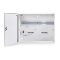
7.1.4 15 VDC Input Termination
Reference: Terminal Strip T1
Terminal strip T1 is used to provide a 15 VDC power to the interface boards (e.g. 4-Reader
board and 8-IO board). It consists of four terminals: two of which are for the input power for
the board (DC 15V IN), and the next two provide the input power for the next board (DC 15V
OUT), within the same casing. The diagram below shows the configuration of the terminal
strip T1.
Figure7.3: Input Terminal
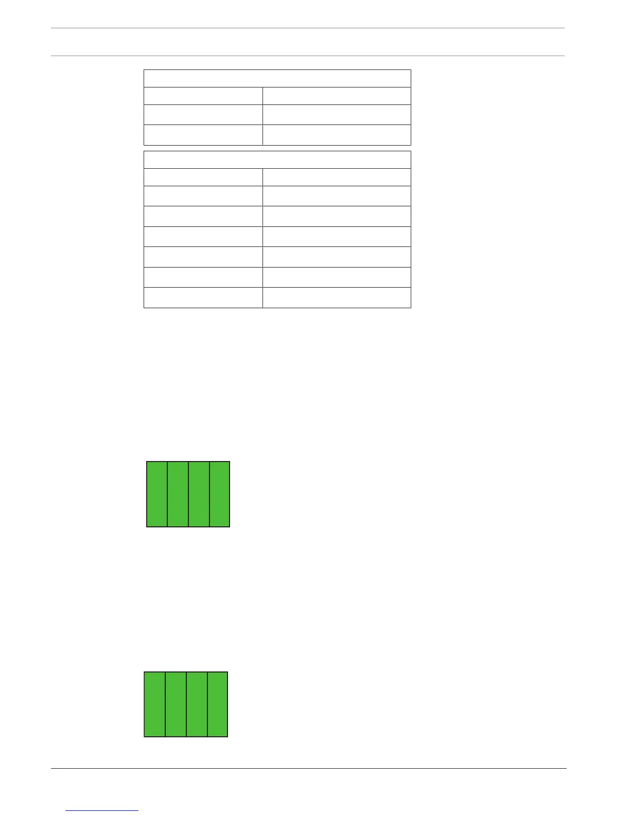
7.1.5 RS232
Reference: Terminal Strip T14
Terminal strip T14 is used as a communication channel between the interface board (e.g. 4-
Reader board and 8-IO board) and the CPU. The channel consists of four data cables, namely
RTS, TX, RX, and Gnd. The cables are connected to the serial COM port on the CPU. The
diagram below shows the configuration of the terminal strip T14.

 Loading...