26 en | 4-Reader Board Access Easy Controller 2.1
2018.11 | 1.0.6 | F.01U.122.796 Hardware Installation Manual Robert Bosch (SEA) Pte Ltd
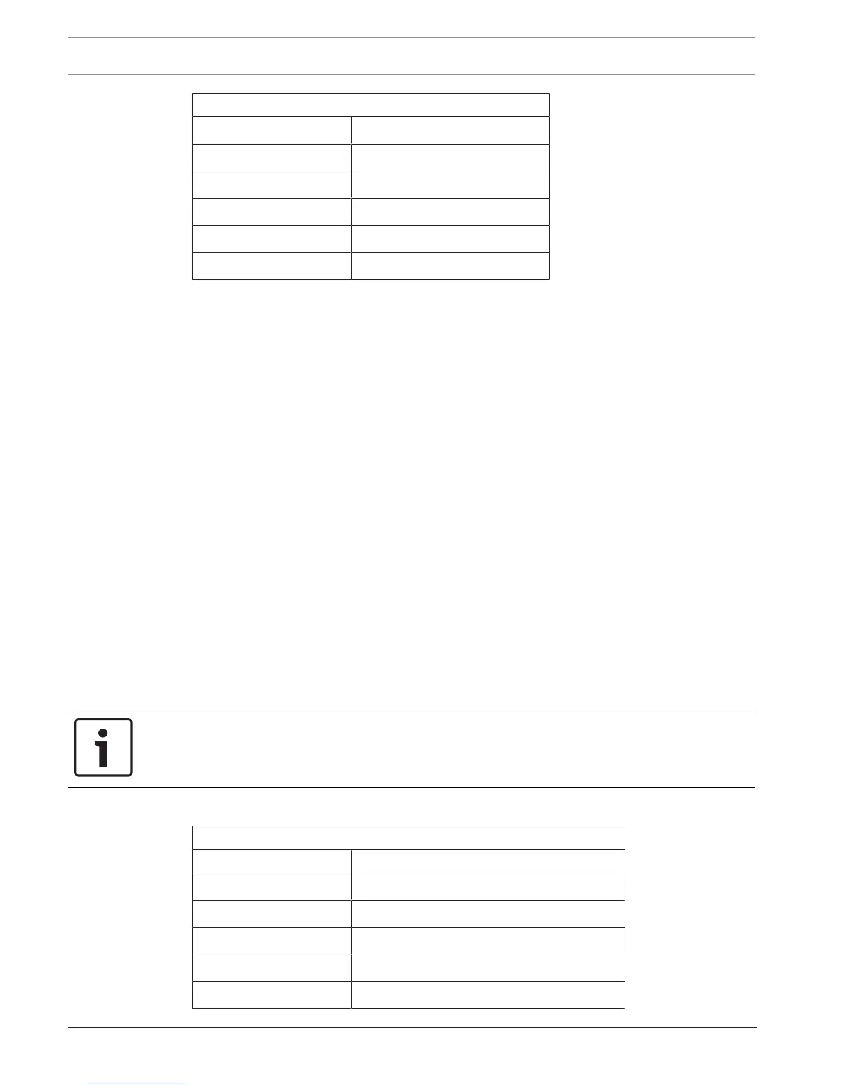
T7 Terminal Strip
IN6 Door contact for reader #3
GND Door contact for reader #3
IN7 Request-to-exit for reader #4
GND Request-to-exit for reader #4
IN8 Door contact for reader #4
GND Door contact for reader #4
6.1.4 Output Connectors
Four 6-pin terminal strips provide connections for door strike and/or magnetic lock control.
The four terminal strips are labelled on the circuit boards as T2, T3, T4 and T5. The output
terminals are Form-C type dry contacts from relays located on the 4-Reader board. Each
output relay provides Normally Closed (N/C), Normally Open (N/O) and a Common terminal
(COM). Each relay also has a corresponding LED, that lights up whenever the relay is
activated.
T2 provides output connection points for readers 1 and 2. T3 provides output connection
points for readers 3 and 4. T4 provides connection points for two spare relays. T5 provides
two spare relay outputs, except on the first 4-Reader board. T5, relay 8 provides a common
alarm output for all Reader boards.
On the first 4-Reader board, the last relay is assigned in the software to provide a common
alarm output from the controller. This relay is intended to provide an easy hand-off by the
controller of an alarm indication to an external burglar alarm system. The common alarm relay
will activate whenever a Door Forced Open or Door Held Open alarm is detected by the
controller. It will also activate when the controller's door tamper circuit is activated, or in
occurrence of an AC power failure.
The common alarm relay will reset when all alarm conditions have returned to normal.
Detailed information concerning the common alarm output is provided in this manual.
Notice!
The contacts of all relays are rated at DC 24V/1A maximum.
The pin configuration for each output connectors is shown in the tables below.
T2 Terminal Strip (top terminal)
Pin# Function
1 Reader #1 (common)
2 Reader #1 (Normally closed)
3 Reader #1 (normally open)
4 Reader #2 (common)
5 Reader #2 (normally closed)

 Loading...