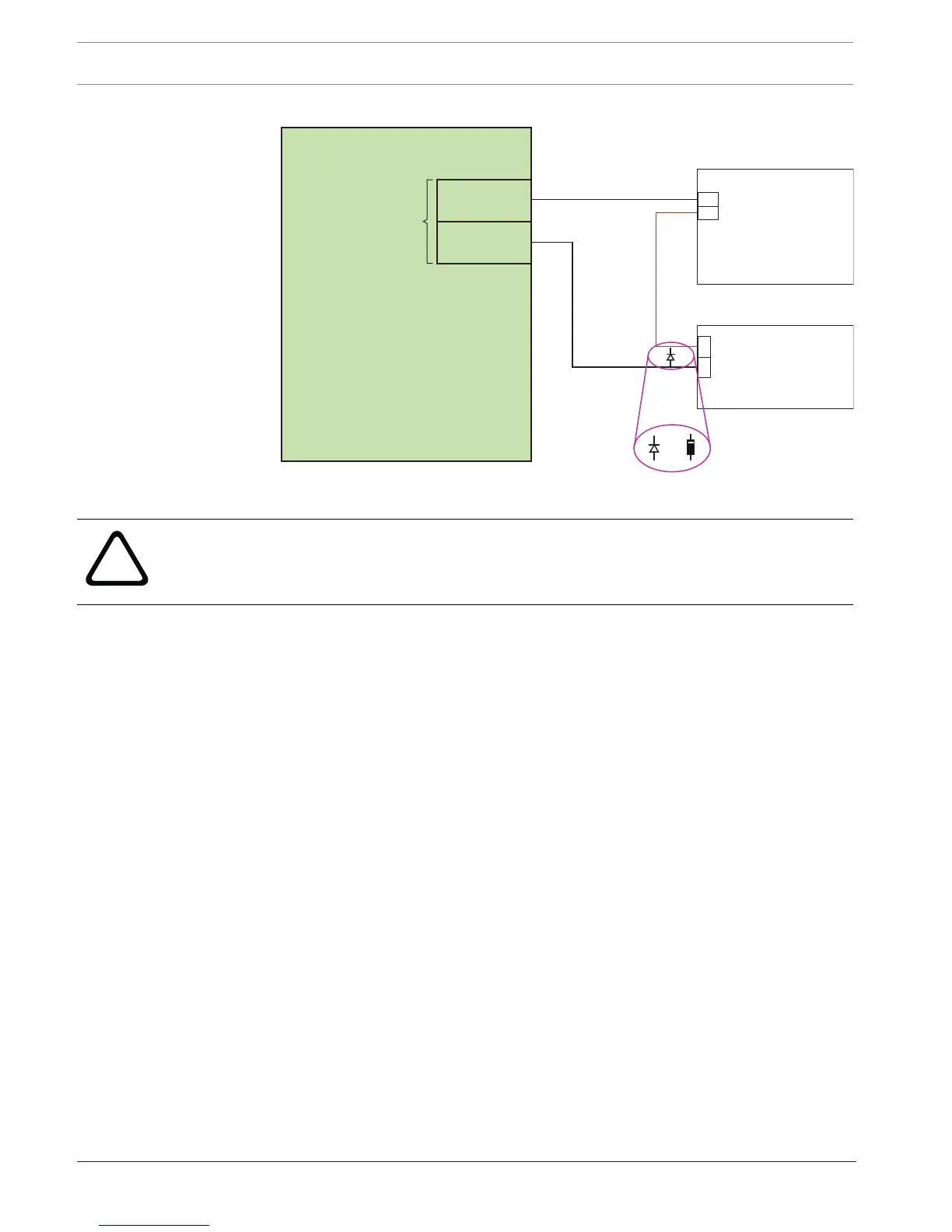
Warning!
Never connect a door strike or magnetic lock circuit to AEC2.1 or any other Access Controller
without installing the protection diode.
3. Mount and wire door contacts and request-to-exit devices.
– Install 6.8K ohm end-of-line resistors at each devices. The resistor should be wired in
parallel (across) normally open devices and in series with normally closed devices.
Refer to door wiring diagrams for additional details.
– When using PIR type request-to-exit devices, be sure to read manufacturers
instructions carefully. Many of these devices need an internal jumper position
changed to work properly in access control applications. Changing this jumper
setting allows the units to quickly reset after they have detected motion. Without
changing the jumper, some devices take up to 30 seconds to reset after they detect
motion. Refer to manufacturer's instruction for additional details.
– Wireless PIR devices are not recommended for use in access control systems and
should not be used as request-to-exit devices on AEC2.1 applications.
4. Wire any output devices that are to be controlled by the controller.
– Output circuits are typically used to control alarm bells, lighting circuits, or similar
equipment.
– The output relays on the AEC2.1 interface boards are designed to handle 1A @ 24
VDC Resistive. If it is necessary to control larger current devices or AC powered
devices, then external interface relays must be installed.
5. Connect all field devices wiring to the 4-Reader and 8-IO boards in the AEC2.1.
– Refer to the device wiring diagrams in this manual to identify the termination points
for the various devices.

 Loading...