Page 13
Figure J
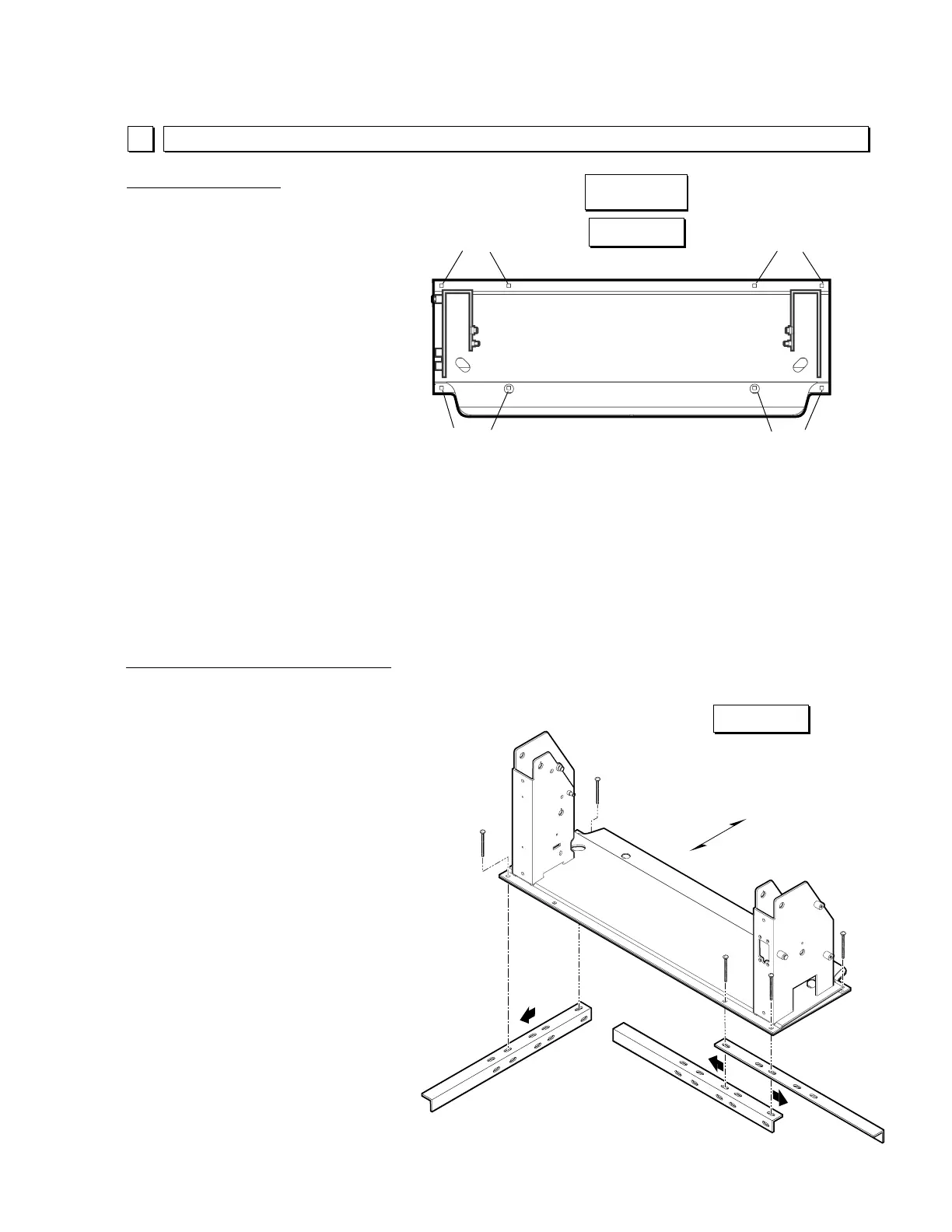
Figure I
Lift Installation Instructions
Base Plate Mounting
There must be a total of eight
3/8"-16 x 4" carriage bolts (or 8"
bolts) securing the base plate
through the floor. Two 3/8"-16
x 8" bolts are supplied for bolting
through vehicle floor framing
members if applicable.
Optimum Bolt Locations: The
mounting bolts must be inserted
in the mounting holes provided in
the base plate. Locate mounting
bolts as shown in Figure I
(straddling the towers). The
holes are positioned straddling
the towers in order to minimize
vertical upright deflection
(details on page 16).
Read warning on opposite
page. Check under the vehicle
for possible obstructions such as
fuel tanks, heat shields, fuel lines,
wires, exhaust, framing members,
etc. Carefully drill eight 3/8"
diameter mounting holes through
the vehicle floor in alignment with
the base plate mounting holes.
Base Plate Wedges: When base
plate wedges are used, the out-
board mounting bolts must be
inserted through the mounting holes
in the wedges (two per wedge).
See Figure H on page 12.
Acceptable Reinforcement Bracket
Positions (typical either end)
2
Lift Securement
Optimum Bolt
Locations
Underfloor Reinforcement Brackets
Two underfloor reinforcement brackets are
supplied. One reinforcement bracket must
be used to secure the base plate below the
floor at both ends of the base plate (unless
inboard base plate mounting bolts penetrate
vehicle chassis subframe members).
OEM van floors are becoming lighter in an
effort to improve weight and fuel efficiency.
1/2" marine grade plywood subfloor is
recommended for use between the lift base
plate and the van floor. Extend the plywood
as far as possible beyond the base plate
footprint to reach key van floor support
points. The mounting surface must be even
and level.
Underfloor reinforcement brackets can be
positioned facing inboard, left or right as
shown in Figure J. The spacing of the
reinforcement bracket mounting holes
matches the mounting hole spacing of
the lift base plate (two standard size
base plates). Two base plate mount-
ing bolts must secure each bracket.
Outboard
Inboard
Mounting
Bolts
Mounting
Bolts
Mounting
Bolts
Mounting
Bolts
Tower
Tower
ONLY
OR
Inboard
Outboard
Base Plate
 Loading...