Page 24
Lift Installation Instructions
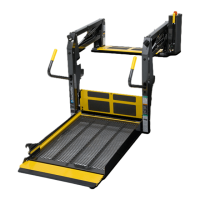
Test Lift Operation
6
Open the door(s) fully, stand
clear and press the orange
UNFOLD switch. Observe all
points of the lift as it unfolds to
be certain that the lift does not
contact the door opening. If any
contact occurs, the lift must be
repositioned.
Press the red DOWN switch to
lower the platform. There must
be a minimum 1" clearance
between the lift and the vehicle
as the platform lowers. The lift
must be repositioned if there is
not a minimum 1" clearance.
Review the Positioning and
Clearance Checklist. Be
certain the lift is properly posi-
tioned and clearance is ad-
equate. The lift must be
repositioned if any contact
occurs!
Repositioning: Loosen or
remove mounting hardware and
carefully reposition the lift if
needed to meet the positioning
and clearance specifications.
Then, bolt the lift in position as
detailed in Step 2.
Review lift securement details in
Step 2 to ensure the lift is
properly mounted.
Note the angle of the platform
when it reaches ground level.
Platform angle must be prop-
erly adjusted. Follow the Plat-
form Angle Adjustment In-
structions on pages 28 and 29
to achieve the proper platform
angle.
Positioning and Clearance Checklist
Vehicle Clearance:
Vertical arms and parallel arms must clear door
opening (vertical sides) as lift unfolds and folds
(see points 1 and 2).
Parallel arms (bottom side) must clear doorsill
when lift is fully lowered (see point 3).
There must be a minimum 1/8" clearance
between the deployed bridge plate and any
obstruction on the vehicle floor (see point 4).
✓
There must be 1/2" clearance between the lift
and the vehicle door(s) when the platform is
completely folded (see point 5).
Lift must clear door-mounted control box when
door is closed (see point 6).
The lift must clear vehicle by minimum 1" (see
point 7).
Design Lifting Capacity
Millennium Series lifts are rated at
a design lifting capacity of 800
pounds. The combination of lift
base plate, mounting bolts,
underfloor reinforcement bars and
the vehicle floor/chassis configu-
ration must support the lift and
the lift load.
Note: Visually check alignment
of towers and vertical arms while
testing lift operation. Refer to the
Positioning and Clearance
Checklist and corresponding
illustrations. Note: Refer to the
Bolt Tightening section and
Figure M on page 16 also. Adjust
tightness of mounting hardware to
maintain proper alignment.

 Loading...
