Page 3
Lift Terminology
Introduction
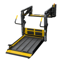
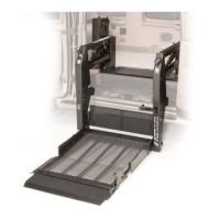
Braun L915 Millennium Series
lifts are ADA compliant and
commercial oriented (intended
for operation by an attendant).
The L915 Millennium Lift Series
includes variations of lift models
L915, L916, L917, L918 and
L919. Model numbers indicate
lift dimensions and options.
Lift model numbers with suffix
“IB” are equipped with an auto-
matic mechanical inboard roll
stop that also serves as the
bridge plate. Lift model numbers
without suffix “IB” feature a
combination stationary inboard
roll stop with an independent
hinged bridge plate. Inboard roll
stop and bridge plate details are
provided in Lift Components (at
right).
L915 Series lift models can be
equipped with left or right side
pump modules as needed. Lift
model numbers with suffix “F”
are right side (front) pump
equipped and model numbers
without suffix “F” are equipped
with a left side (rear) pump. A
left side pump-equipped lift
model is depicted in the Lift
Terminology Illustration. Right
side pump lift models are a
mirrored image of rear pump
models (pump module located on
opposite end of base plate).
Refer to the Lift Terminology
Illustration for identification of lift
components.
Lift installation and lift operation
procedures are identical for all
L915 Series lift models. Read
and become familiar with the lift
operating instructions appearing
on lift-posted operating instruc-
tions decals and the lift installa-
tion instructions contained in this
manual before beginning installa-
tion procedures.
Terminology: Become familiar
with the terminology that will be
used throughout this manual.
Become familiar with the identifi-
cation of lift components and their
functions. Contact your lift sales
representative or call The Braun
Corporation at 1-800-THE LIFT if
any of this information is not fully
understood.
Direction: The terms "left (rear),"
"right (front)," "inboard," and
"outboard" will be used throughout
this manual to indicate direction
(as viewed from outside the
vehicle looking directly at the lift).
Refer to the Lift Terminology
Illustration for clarification of
direction terms.
Lift Components
Pump Module: The lift-mounted
pump module consists of the
hydraulic pump, the manual hand
pump and electrical components
that power the lift electric/hydraulic
systems. Note: A green power/
interlock indicator light is built into
the pump module (details on page
41).
Hand-held Switch Control Box:
The “quick-disconnect” hand-held
control switchbox is connected to
the pump module. “Quick-discon-
nect” hand-held controls are
available with three types of cable
(standard, armored and coiled).
The control box is equipped with
two color-coded rocker switches,
(UNFOLD/FOLD and DOWN/UP).
The switches activate the auto-
matic lift functions.
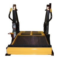
Lift Frame: The lift frame con-
sists of the base plate, two towers,
the parallel arms, the vertical
arms, platform pivot arms and the
handrails. The two main hydraulic
cylinders are housed in the
parallel arms. The electrical/
hydraulic powered lift frame
components mechanically unfold,
lower, raise and fold the lift platform
assembly.
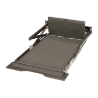
Platform Assembly: The lift
platform assembly consists of the
steel tubing frame with grating
surface upon which the wheelchair
is positioned, the outboard roll
stop, roll stop latch, the inboard roll
stop, and the hydraulic cylinder
assembly that powers the outboard
roll stop.
Lift-Tite
™
Latch: The spring
loaded latches prevent the platform
from unfolding from the stowed
position in event of platform drift.
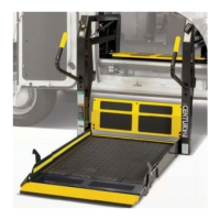
Outboard Roll Stop: The cylin-
der-powered automatic outboard
roll stop provides a ramp for
wheelchair loading and unloading
at ground level.
Roll Stop Latch: The spring-
loaded latch locks the outboard roll
stop in the vertical position when
the platform raises above ground
level.
Automatic Inboard Roll Stop and
Bridge Plate (IB): L915 “IB” lift
models are equipped with an
automatic mechanical inboard roll
stop that also serves as the bridge
plate (shown in the Lift Terminology
Illustration on page 2). The me-
chanical roll stop/bridge plate
automatically rotates from the
horizontal (bridging) position to the
vertical (roll stop) position as the lift
lowers and raises.
Fixed Inboard Roll Stop: A
stationary inboard roll stop is built
into “non-IB” L915 lift platforms.
Independent Hinged Bridge
Plate: “Non-IB” L915 lift models
are equipped with an independent
hinged bridge plate (shown in the
Lift Terminology Illustration on page
2). The bridge plate bridges the
gap between the lift platform and
the vehicle floor.
 Loading...