Page 55
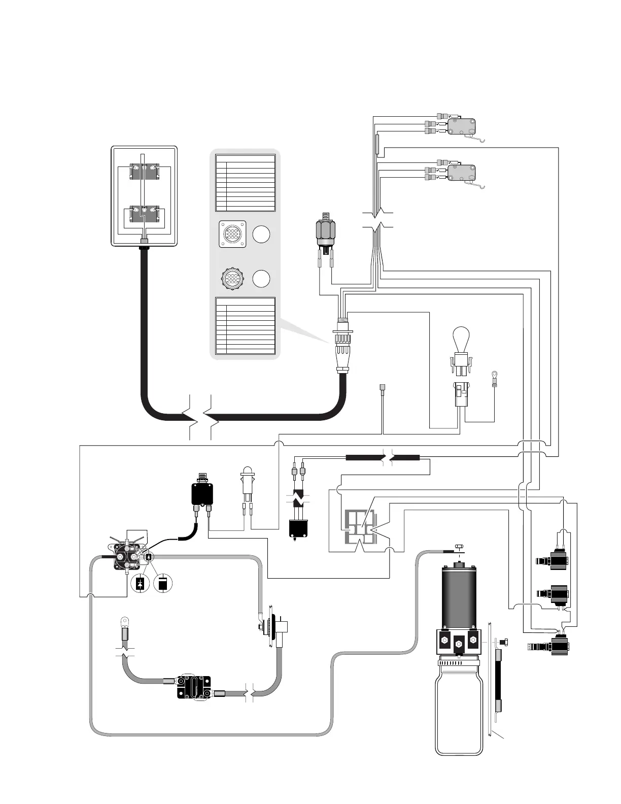
Lift Wiring Diagram
Note: Applicable
for 16 gauge wiring
harness control
boxes. See page
56 for 18 gauge
harness control
box wiring diagram.
BK
Y
GN
PIN #1
W/BK
GN
GN
GN
GN
BK
BK
BU
BK
BK
BK
W
W
W
GY
GY
Bridge
Down
Unfold
BK
BU
W
R
R
R
R
R
R
R
R
Y
Y
GY
PK
PK
PK
Y
Y
R
Pump Ground
R
Interlock
Jumper
To
Remote
Interlock
Ground
Fold/Unfold
Switch
Unfold / Down
Microswitch
Pump-Mounted
Platform Sensor
Pressure Switch
C-H
COM
NO
NC
N.O.
N.C.
COM.
Up / Fold
Microswitch
C-H
COM
NO
NC
N.O.
N.C.
COM.
PIN #2
BU BU
GY
GY
Y
Y
GY
GY
GY
GN
BK
W
BN
Up/Down
Switch
BU
W
W
Y
GY
GY
Y
Y
BU
W
BU
GY
BU
BK
BN
Note: Shown with lift in stowed position.
NOT USED
GREEN - 6 COND.
WHITE - 6 COND.
BROWN - 6 COND.
YELLOW - 6 COND.
BLACK - 6 COND.
NOT USED
NOT USED
NOT USED
6
5
4
3
2
1
COLORNO.
9-COND WIRE CODE
7
8
9
NOT USED
GREEN
WHITE
BROWN
YELLOW
BLACK
NOT USED
NOT USED
NOT USED
6
5
4
3
2
1
COLORNO.
9-COND WIRE CODE
7
8
9
Bridge
Microswitch
Pump
Mounting
Plate
Switch Box
(As Viewed From Terminal
Side of Switch)
123
456
789
321
654
987
N.O.
N.C.
COM.
(Side view of solenoids
removed from pump.)
Bridge
Relay
COM
NO
NC
Hydraulic
Pump
Bridge
Down
Unfold
Circuit Sentry
(Circuit Breaker)
Bat.
Aux.
Lift
Power Cable
Pump Module
Power Feed
Connects to
Vehicle Battery
(+) Positive Post
#13362A
Lead Wire
BU
or
Note polarity of diode. It
must be oriented as shown.
Detail at left shows two different
styles of diode identification.
R
R
R
R
Up/Fold
Solenoid
Motor Power Feed Wire
Circuit
Breaker
B
A
T
A
U
X
W
Power / Interlock
LED
+
-
Note: Shown with lift in stowed position.
 Loading...