Page 61
16
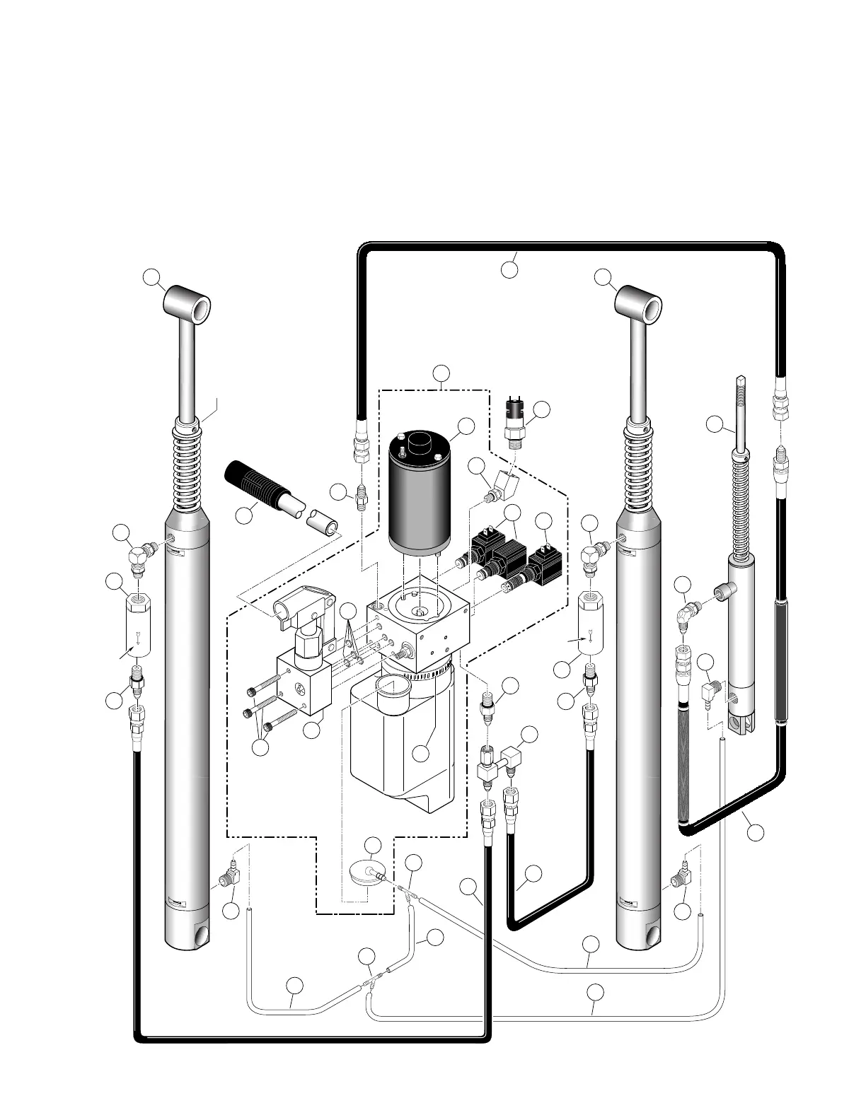
Opposite Pump Side Cylinder
Hydraulic
Pump
Manual
Backup
Pump
Arrow must
face pump
18
17
12
19
20
11
10
9
15
5
Arrow must
face pump
17
18
16
12
13
12
12
7
6
1
26
27
2
14
3
8
21
22
22
21
Hydraulic
Pump Motor
4
25
Roll Stop Cylinder
24
Pump Side Cylinder
28
23
7
21
Front Pump Hydraulics Diagram
Note: See pages 58 and 59 for Rear Pump Hydraulic Diagram and Parts List.
Note: See page 57 for L915 Hydraulic Schematic.
Note: Illustrations depict components as equipped when specified lift series was in production. Replace-
ment components such as hose assemblies will typically reflect the most current configuration.
Collars not present on
42" Floor-to-Ground
lift models.
 Loading...