CHAPTER 2 STANDARDS AND ADJUSTMENTS
2-25
3.5.2 Adjusting the Potential Sensor
The potential sensor and the po-
tential control PCB are adjusted
in a pair, requiring simultaneous
replacement.
1) Start service mode, and set ‘0’ to the
following to disable potential control:
COPIER>OPTION>BODY>PO-CNT.
2) Replace the potential control PCB.
3) Connect the connector of the potential
sensor to the connector of the machine.
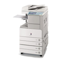
4) Fit the potential checking electrode
(FY9-3012) [2] to the potential sensor
[1].
F02-203-22
When fitting the checking elec-
trode to the potential sensor [2],
be sure that the magnet of the
checking electrode does not
come into contact with the po-
tential sensor cover.
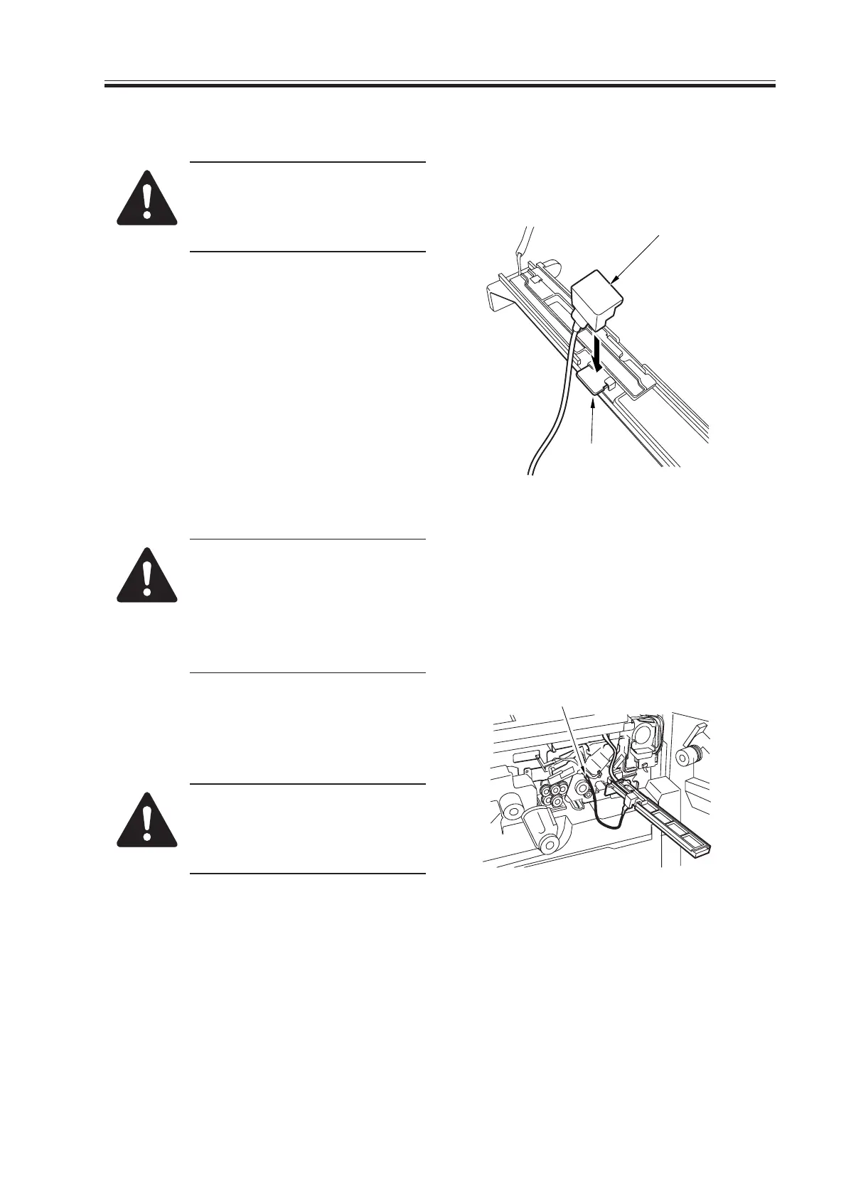
5) Connect the clip [3] of the checking
electrode to the frame of the machine
(GND).
Be sure to keep the clip [3] fully
away from the sensor and not to
bring it in contact with the cover
of the sensor.
F02-203-23
[2]
[1]
[3]

 Loading...