2-53
CHAPTER 2 STANDARDS AND ADJUSTMENTS
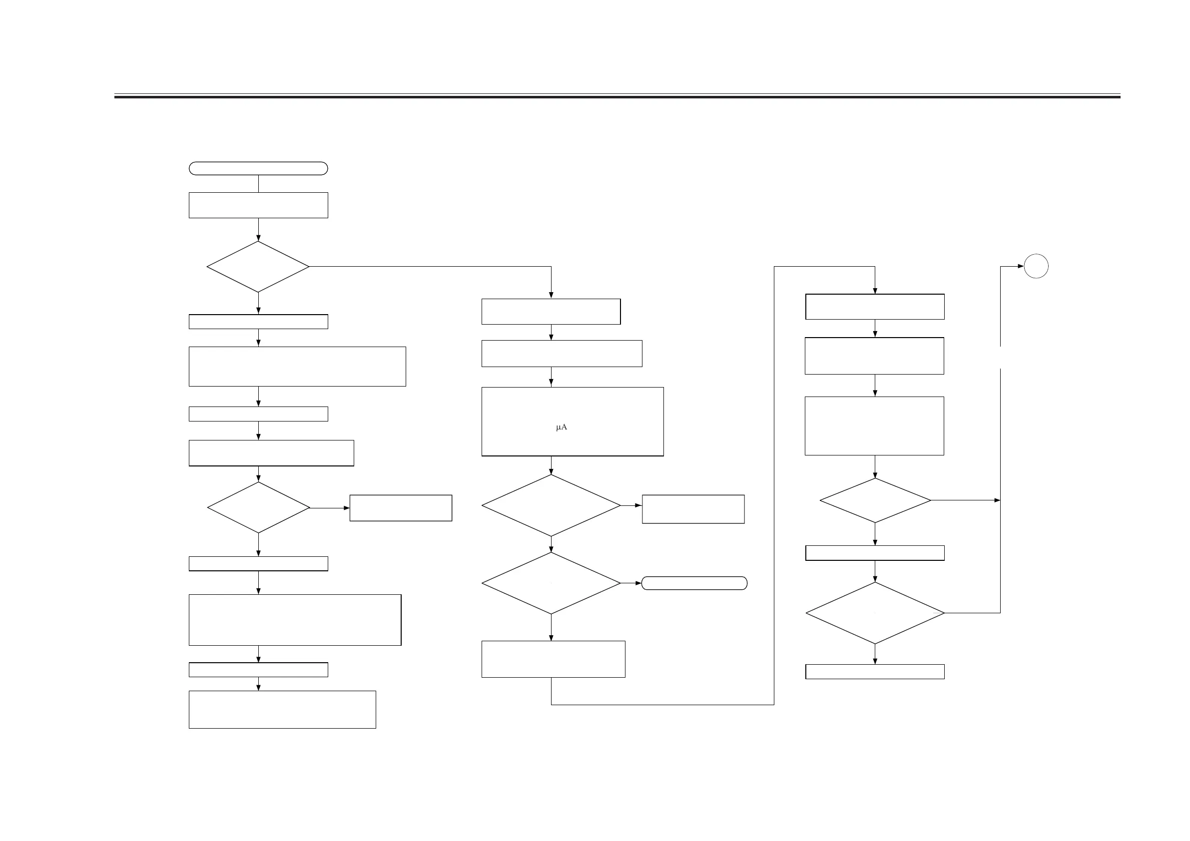
8.4 Checking the Potential System
Turn off the main power switch.
1) Short CP106 and CP105 on the DC controller PCB.
2) Disconnect the connector (J9010) used to connect between
the DC controller PCB and the potential control PCB.
1) Disconnect the cable used to short CP106 and CP105 on
the DC controller PCB.
2) Connect the connector (J9010) used to connect between
the DC controller PCB and the potential control PCB.
Check to make sure that the potential control PCB is
supplied with power; then, check the potential sensor
using the electrode designed for making checks.
Turn off the main power switch.
Turn on the main power switch.
Forced execution
of potential control
Enable potential control: COPIER>
OPTION>BODY>PO-CNT=1.
Check the laser output.
Replace the laser unit.
START
NO
YES
NO
YES
YES
NO
Turn on the main power switch.
NO
Checking the Laser Output
Is the image better?
A
Is the laser output a
limit value?
YES
Replace the photosensitive drum. If the
problem is not corrected, go to the
checking the laser output.
Make the following selections in service mode
(level of current of the primary charging assembly):
COPIER>DISPLAY>HV-STS>PRIMARY.
Convert the reading (
m
A) indicated during printing
into a control voltage with reference to 8.5
"Potential Control Conversion Table."
YES
NO
YES
Is the
difference between
the actual measurement of
PR-CNT and 'PRIMARY' in
service mode ±
10%?
NO
Replace the
high-voltage transformer. Is
the problem corrected?
Checking the Primary Output
Replace the DC controller
PCB.
Replace the DC controller
PCB.
Is the reading
between 0 and 30?
END
Make the following selections in
service mode, and enter '1':
COPIER>FUNCTION>DPC>DPC.
Is the indication
70 ± 15 V?
Check the following indications:
for copier images:
COPIER>DISPLAY>DPOT>VL2M
for printer images:
COPIER>DISPLAY>DPOT>VL2M-P
Disable potential control: COPIER>
OPTION>BODY>PD-CNT=0
Make the following selections in service mode:
COPIER>DISPLAY>DPOT>DPOT-K.
Disable potential control: COPIER>
OPTION>BODY>PO-CNT=0
Measure the voltage PR-CNT during copying
of J102A-11 on the DC controller PCB.

 Loading...