12
ENG
c.pCO sistema +0300057EN rel. 1.2 - 29.05.2017
Display (c.pCO Small...Extralarge)
Two displays are available:
• the main display on the built-in terminal (if featured);
• the secondary display, which shows the controller pLAN address.
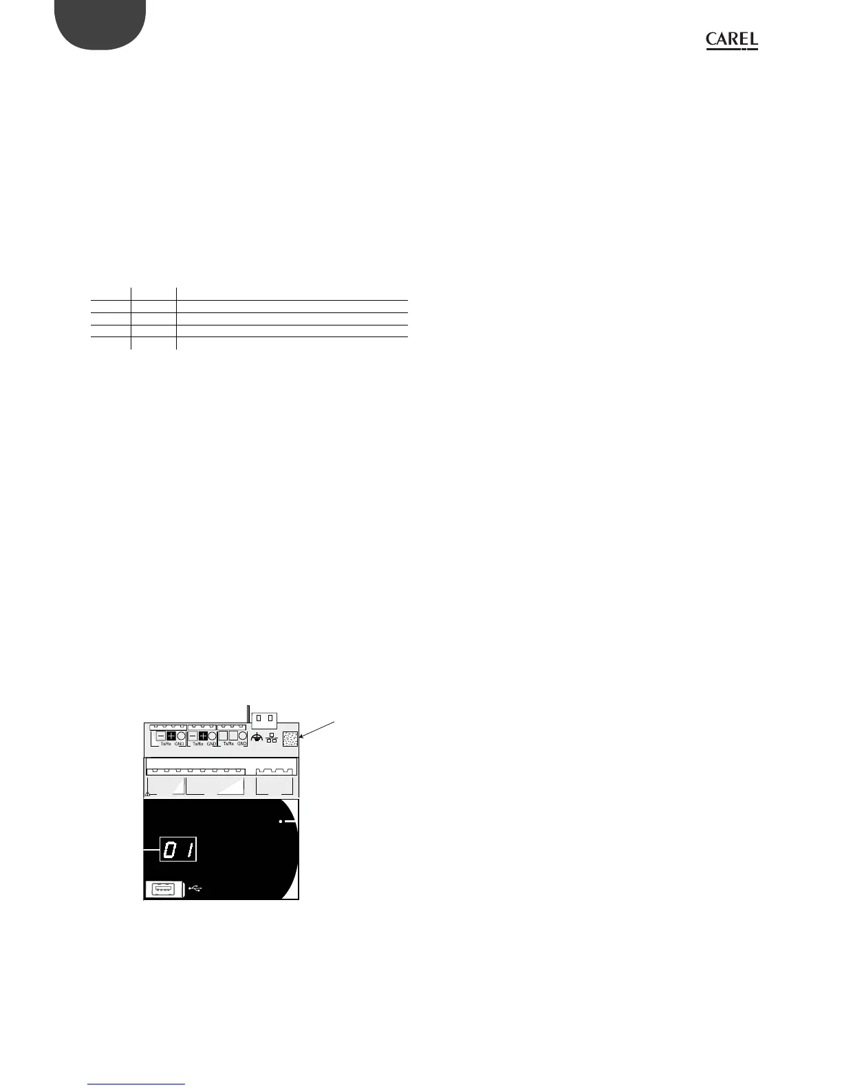
Display (c.pCOmini)
A built-in display is available (if featured), or a secondary display that
displays the controller pLAN address.
LED (c.pCO Small...Extralarge)
Six LEDs are featured:
• 1 yellow LED indicating that the device is powered;
• 1 red LED indicating an overload on the +VDC (J2-5) terminal;
• 4 LEDs indicating valve status (only on c.pCO built-in driver models).
Flashing LEDs mean the valve is moving; steady on LEDs mean the
valve is completely open or closed.
LED Colour Description
A Yellow close valve A (connector J27)
B Green open valve A (connector J27)
C Yellow close valve B (connector J28)
D Green open valve B (connector J28)
Microswitches (c.pCO Small...Extralarge)
Four microswitches are provided to congure port J26 as a Fieldbus or
BMS port (see “Port J26 conguration”).
USB ports
c.pCO Small...Extralarge
The controller features two USB ports, which can be accessed after
removing the cover in order to performe operations such as loading the
application program and the operating system, saving the logs, etc.
• a “host” USB port for connecting pendrives;
• a “device” USB port for direct connection to the USB port of a computer.
c.pCOmini
c.pCOmini models features a single micro USB port for operations such
as loading the application program and the operating system, saving the
logs, etc.
• the same USB port acts both as “host” port for connecting a USB ash
drive, as well as “device” port for direct connection to a computer.
Mac Address label
Label with QR code containing the Mac Address that uniquely identies
the controller on the Ethernet network
NO1
C1/2
NO2
NO3
C3/4/5
NO4
C3/4/5
NO5
NO6
NC6
C6
J10 J11 J12
J3 Disp.
+Vter m
J4 FBus J5 CAN
LH
Mac Address
Fig. 2.b
 Loading...


