34
ENG
c.pCO sistema +0300057EN rel. 1.2 - 29.05.2017
c.pCO Small...Extralarge: 0 to 10 V analogue outputs
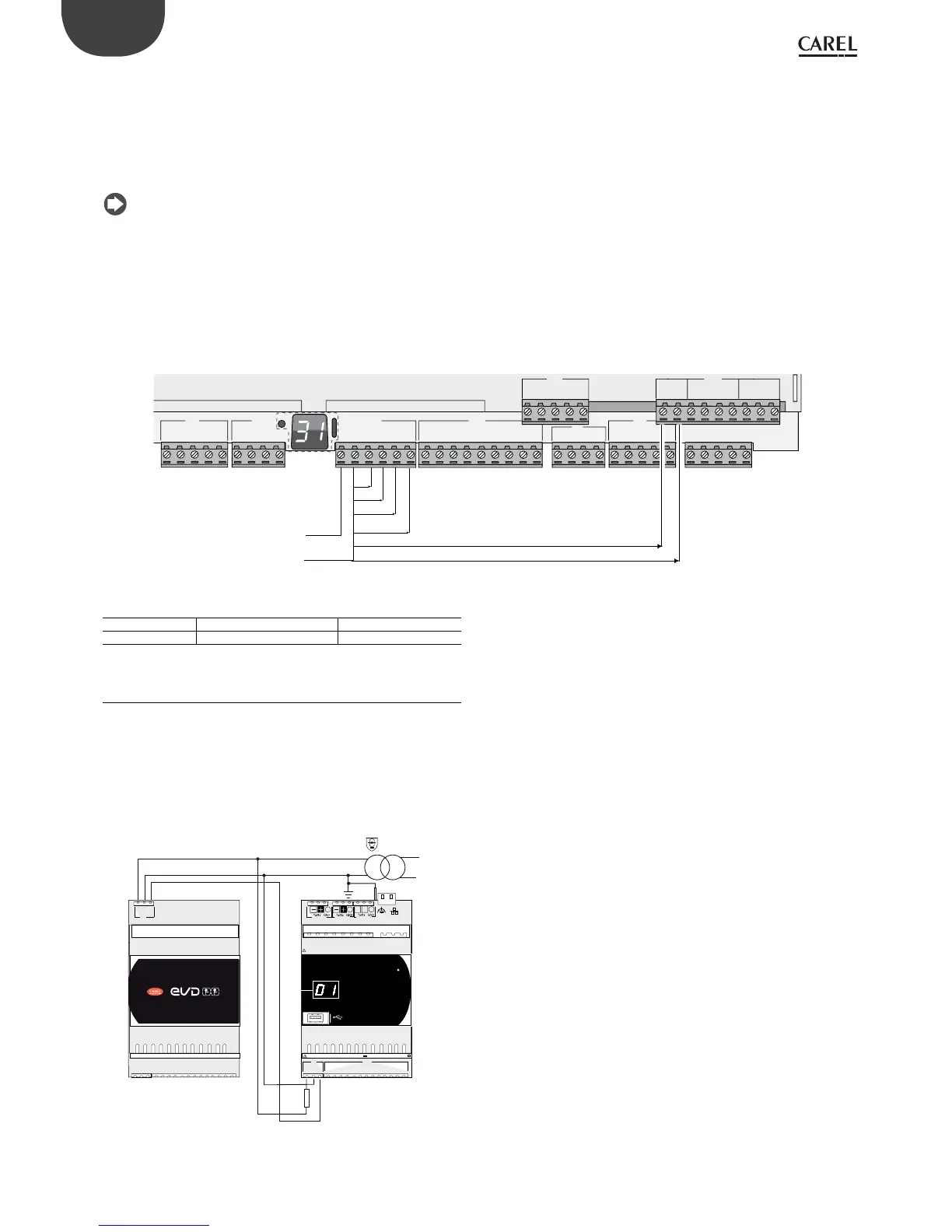
On terminals VG and VG0 the controller provides optically-isolated 0 to 10
V analogue outputs, to be powered externally at the same voltage as the
controller, i.e. 24 Vac or 28 to 36 Vdc. The connection diagram is shown
in the gure below. The 0 V supply voltage is also the voltage reference
of the outputs. See the Technical Specications table for details on the
output current, output impedance, etc. (see chap. 12).
Note:
• the analogue output can be connected to the CONVONOFF0 module
to convert the 0 to 10 V output into an ON/OFF relay output;
• a 0 to 10 Vdc analogue output can be connected in parallel to other
outputs of the same type, or alternatively to an external voltage
source. The higher voltage will be considered. Correct operation is not
guaranteed if actuators with voltage inputs are connected;
• if optical isolation is not required, the VG-VG0 analogue outputs can be
powered at the same voltage on G-G0: connect G0 to VG0 and G to VG.
Example connection diagram (LARGE model):
U1
U2
U3
GND
+VDC
U4
GND
U5
GND
VG
VG0
Y1
Y2
Y3
Y4
ID1
ID2
ID3
ID4
ID5
ID6
ID7
ID8
IDC1
U6
U7
U8
GND
ID9
ID10
ID11
ID12
I DC9
ID13H
ID13
IDC13
ID14
ID14H
J2 J3
J4 J5 J7
J8
J20
J6
19
ID15H
ID15
IDC15
ID16
ID16H
Y5
Y6
ID17
ID18
IDC17
U9
GND
U10
GND
FieldBus card BMS card
24 Vac / 28...36 Vdc
0 V
ID1
ID2
ID3
ID4
ID5
ID6
ID7
ID8
IDC1
ID9
ID10
ID11
ID12
IDC9
ID13H
ID13
IDC13
ID14
ID14H
Vout
Vout
Vout
Vout
Vout
Vout
Fig. 5.u
Maximum number of optically-isolated analogue outputs (ref. VG0)
c.pCO model Small/Medium/Extralarge Large
Outputs Y1, Y2, Y3, Y4 Y1, Y2, Y3, Y4, Y5, Y6
5.5 Connecting the Ultracap module
The Ultracap module can be connected to power the controllers in the event
of blackouts:
1. c.pCOmini controller: the module guarantees temporary power to
the controller and driver for enough time to close the electronic
valve (40s with forced closing of the valve, 60s without forced closing
of the valve). NB: with Vdc power supply, forced closing of the
electronic expansion valve is not managed in the event of blackouts.
2,5 AT
24 Vac
230 Vac
40 VA
U1
U2
U3
GND
U4
U5
U6
GND
U7
U8
U9
U10
GND
J1
J2
G
G0
Vbat
G/G0: 24 V~ 50...60 Hz / 28...36 V 30 VA/12W
J3 Disp.
+Vter m
J4 FBus J5 CAN
LH
Ultracap Technology
G
G0
Vbat
Fig. 5.v
 Loading...


