38
MINI
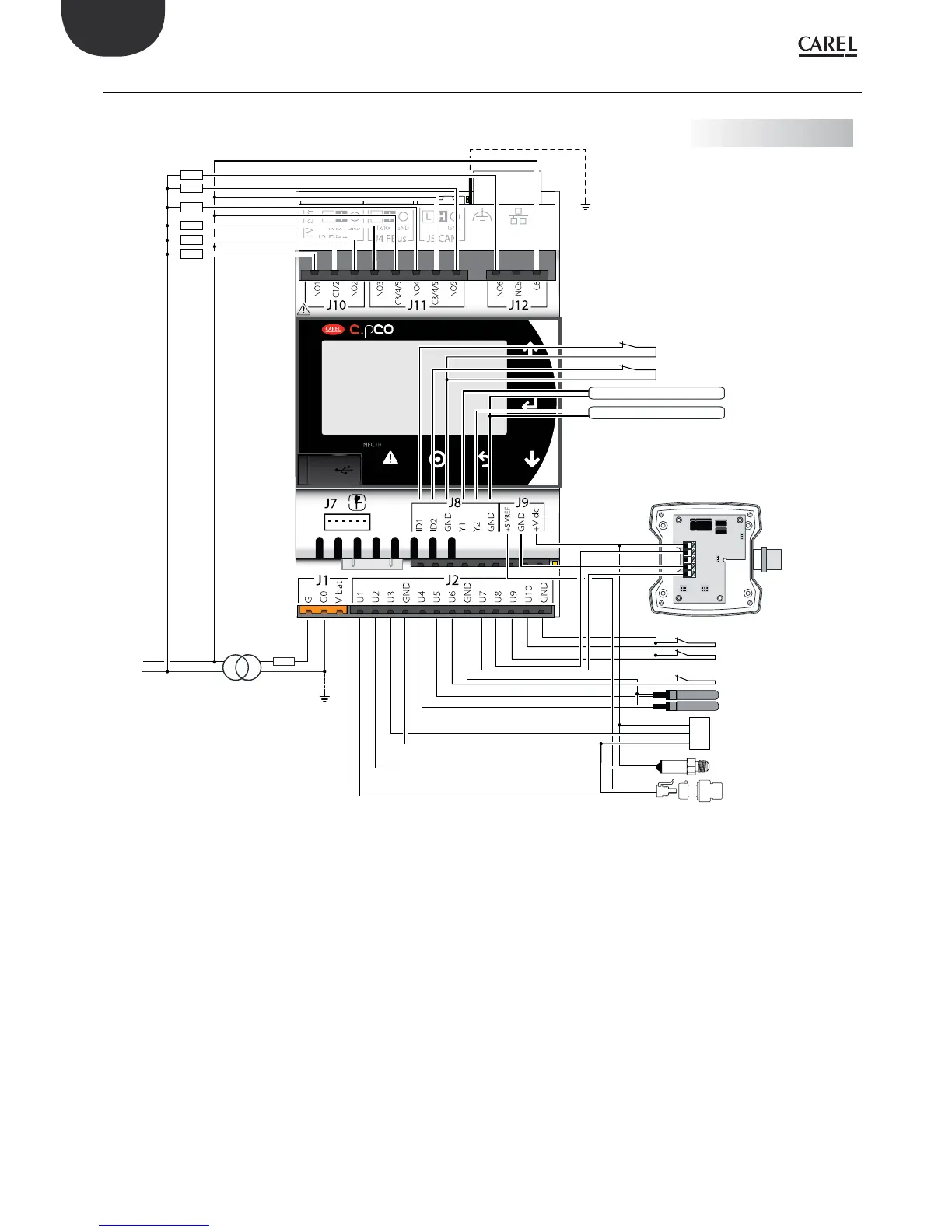
digital input 1
digital input 2
out H
M
NTC
NTC
+ (G)
probe 7-8
probe 4 Carel NTC
probe 5 Carel NTC
probe 6 voltage-free/digital input
probe 9 voltage-free/digital input
probe 10 voltage-free/digital input
probe 1 (0/5V)
230/24 Vac
L
N
2,5 A T
analog output 1 (0...10 Vdc)
analog output 2 (0...10 Vdc)
M
OUT
+V
probe 2 (4/20 mA)
probe 3 (0/1 Vdc or 4/20 mA))
digital output 1
digital output 2
digital output 3
digital output 4
digital output 5
digital output 6
ENG
c.pCO sistema +0300057EN rel. 1.2 - 29.05.2017
5.9 General connection diagram c.pCOmini
Fig. 5.ae
 Loading...


