13
ENG
c.pCO sistema +0300057EN rel. 1.2 - 29.05.2017
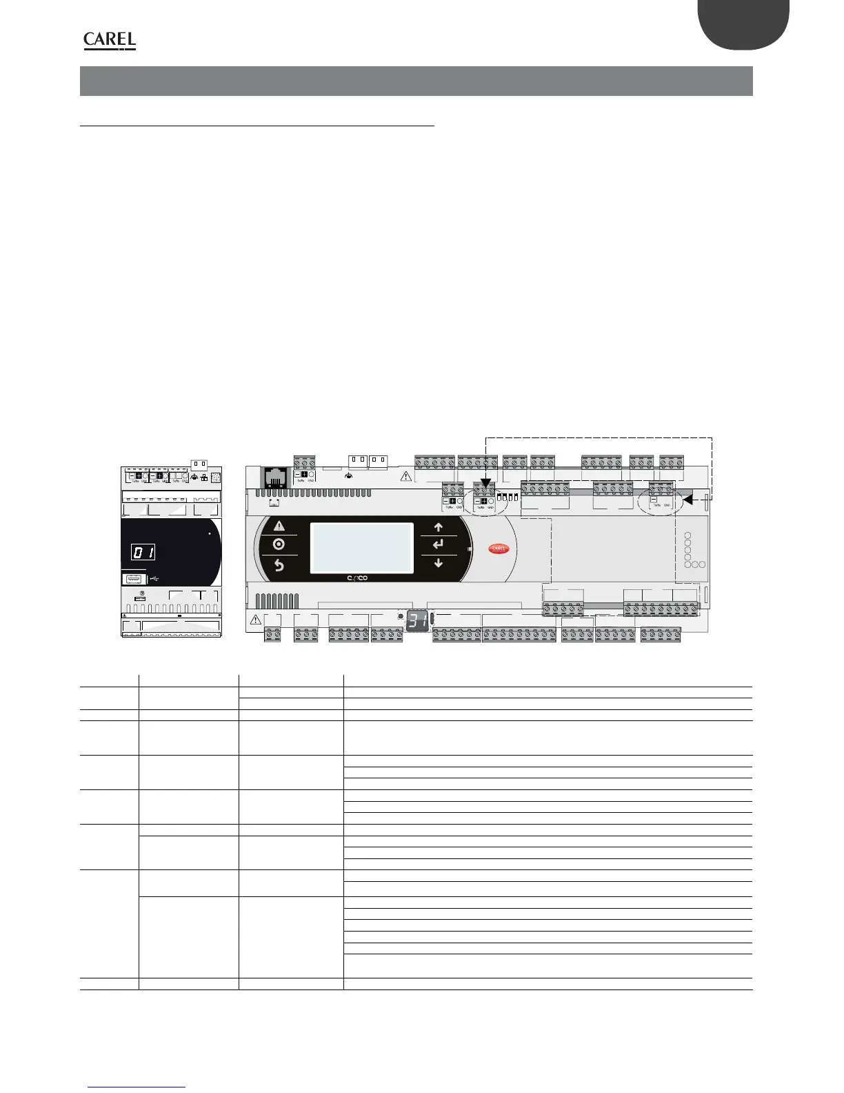
3. COMMUNICATION PORTS
3.1 Serial ports
c.pCO Small...Extralarge
The controllers come with ve serial ports:
• a terminal port on connector J10-J11 (pLAN)
• a built-in BMS port on connector J25 (BMS2)
• a built-in Fieldbus port on connector J26 (FBus2).
• a BMS port to be used with the c.pCO family BMS expansion card (BMS1)
• a FieldBus port to be used with the c.pCO family BMS expansion card (FBus1)
On the c.pCO Large and Extralarge version, connector J23 is available, marked
FBus2, in the same way as connector J26. From the point of view of application
program management, this is the same serial line, so dierent addresses must be
used for devices connected to both connectors, while from the electrical point of
view the ports are independent (an electrical fault on port J26 does not aect port
J23). See the “Technical Specications” table (chap.
12).
c.pCOmini
The controller features:
• a terminal port on connector J3 (Disp.)
• a built-in BMS port on connector J6 (BMS, only on the c.pCOmini Enhanced
model)
• a built-in Fieldbus port on connector J4 (FBus, on the c.pCOmini Enhanced and
High End models).
C1
NO1
NO2
NO3
C1
C4
NO4
NO5
NO6
C4
C7
NO7
C7
NO8
C8
NC8
NO12
C12
NC12
NO13
C13
NC13
C9
NO9
NO10
NO11
C9
G
G0
U1
U2
U3
GND
+VDC
+Vterm
GND
+5 V
REF
U4
GND
U5
GND
VG
VG0
Y1
Y2
Y3
Y4
ID1
ID2
ID3
ID4
ID5
ID6
ID7
ID8
IDC1
U6
U7
U8
GND
ID9
ID10
ID11
ID12
IDC9
ID13H
ID13
IDC13
ID14
ID14H
J1
J24 J2 J3
J4
J5 J7
J8
J20
J21
J14
J10
J13
J12
J22
J16
J17
J18
J15
J6
J19
NO14
C14
NC14
NO15
C15
NC15
C16
NO16
NO17
NO18
C16
ID15H
ID15
IDC15
ID16
ID16H
Y5
Y6
ID17
ID18
IDC17
U9
GND
U10
GND
FieldBus card BMS card
J23 FBus2
J11 pLAN
J25 BMS2
J26 FBus2
43 2 1
ONLY FOR
LARGE AND EXTRALARGE
MODELS
U1
U2
U3
GND
U4
U5
U6
GND
U7
U8
U9
U10
GND
J1
J2
G
G0
Vbat
NO1
C1/2
NO2
NO3
C3/4/5
NO4
C3/4/5
NO5
NO6
NC6
C6
+5VREF
GND
+V dc
J9
J10 J11 J12
G/G0: 24 V~ 50...60 Hz / 28...36 V 30 VA/12W
J3 Disp.
+Vter m
J4 FBus
Y1
GND
ID2
ID1
Y2
GND
J8
J7
J5 CAN
LH
000A5C*
Fig. 3.a
Interface Type/Connectors Control Features
Ethernet RJ45 c.pCOmini High End
• one 10/100 Mbps Ethernet port
c.pCO Small...Extralarge
• two equivalent 10/100 Mbps Ethernet ports (100-BASE TX standard)
Serial ZERO J3 Disp. c.pCOmini
• Integrated on main board
Serial ZERO pLAN/J10, J11 c.pCO Small...Extralarge
• HW driver: asynchronous half duplex RS485 pLAN
• Not optically-isolated
• Connectors: telephone jack + 3-pin plug-in connector (4-pin plug-in connector only on c.pCOmini)
Serial ONE BMS 1 Serial Card c.pCO Small...Extralarge
• Not integrated on main board
• HW driver: not present
• Can be used with all c.pCO family BMS expansion cards
Serial TWO FieldBus 1 Serial Card c.pCO Small...Extralarge
• Not integrated on main board
• HW driver: not present
• Can be used with all c.pCO family Fieldbus expansion cards
Serial THREE J6 BMS c..pCOmini Enhanced
• Integrated on main board
BMS 2 / J25 c.pCO Small...Extralarge
• HW driver: asynchronous half duplex RS485 Slave
• Optically-isolated/non-optically-isolated serial port
• 3-pin plug-in connector
Serial
FOUR
J4 FBus c.pCOmini Enhanced
and High End
• Integrated on main board
• HW driver: asynchronous half duplex RS485 Master
FieldBus 2 / J26
(and J23 Large - Extra-
large version)
c.pCO Small...Extralarge
• Integrated on main board
• HW driver: asynchronous half duplex RS485 Master or Slave (see par. " J26 port conguration")
• J23: not optically-isolated
• J26: optically-isolated/not optically-isolated
• 3-pin plug-in connector
• J23 and J26 are both managed by the same protocol as serial 4, with the advantage of being
electrically independent.
Tab. 3.a
 Loading...


