19
ENG
c.pCO sistema +0300057EN rel. 1.2 - 29.05.2017
4.5 Connecting the terminal
c.pCOmini
Use the accessory cable P/N S90CONN0S0, connected as shown in the
gure. The maximum distance allowed between controller and terminal
is 10 m.
od. S90CONN0S0
BIANCO-WHITE/BLU = +Vterm
NERO-BLACK/ GIALLO-YELLOW = GND
ROSSO/RED = -
VERDE/GREEN = +
J3 Disp
+Vterm
BIANCO/WHITE
NERO/BLACK
ROSSO/RED
BLU
GIALLO/YELLOW
VERDE/GREEN
J3 Disp
+Vterm
Fig. 4.k
c.pCO Small...Extralarge
The controller and the terminal are connected to a pLAN network.
1: Connecting the terminal to one c.pCO controller
When connecting the controller to the terminal, the following restrictions
should be kept in mind:
1. the overall length of the pLAN network should not exceed 500 m.
Consequently, if the terminal is installed in a remote position, the
length of the terminal cable must be included in the total length;
2. the unshielded telephone cable can be used for a max. length of
50 m. Beyond this length, use a 3-wire shielded cable (see the table
below);
3. for lengths greater than 200 m, the power supply for the terminal
must be provided separately;
4. no more than 3 terminals can be connected to the same c.pCO
controller. The terminals must be the same type (e.g. all pGD1).
One terminal is powered by the controller, and the other two by an
external power supply.
Important:
• in domestic installations, standard EN55014 requires the connection
cable between the controller and the terminal to be shielded, with the
shield earthed at both ends;
• in industrial installations with length >10 m, the connection cable
between the controller and the terminal must be shielded and the
shield must be earthed.
Case A: 1 terminal.
A.1: distance L < 50 m.
The typical connection for one terminal (e.g. PGD1) is made using a 6-wire
telephone cable available from CAREL as an accessory (S90CONN00*).
The telephone connector provides both data transmission and the
power supply for the terminal.
To make the connection:
• plug the connector into terminal J10 until it clicks into place.
To remove the connector:
• press lightly on the plastic catch on the connector and pull it out.
L < 50 m
cavo telefonico
telephone cable
J10
J11 pLAN
Fig. 4.l
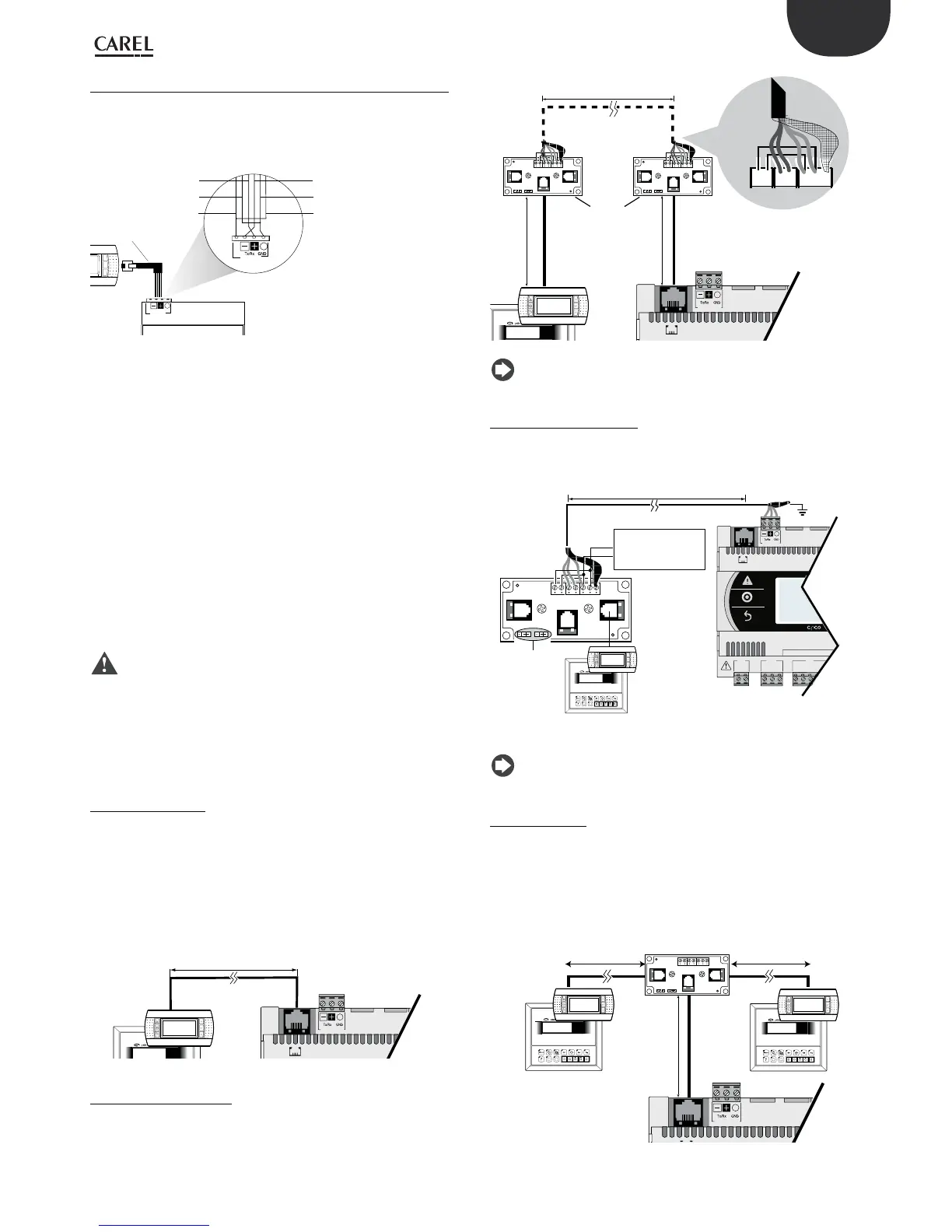
A.2: distance 50< L< 200 m.
Lengths greater than 50 m require two TCONN6J000 cards connected
with a 4-wire shielded cable, as shown in the gure. The terminal is
powered by the controller.
J10
J11 pLAN
L < 200 m
0,8 m MAX
0,8 m MAX
cavo telefonico
telephone cable
Cavo schermato
AWG20/22
2 twisted pair
6
++TX
RX
TX
RX
-
+-
-
5 4 321 0
TCONN6J000
6 5 4 321 0
6 5 4 321 0
cavo telefonico
telephone cable
Fig. 4.m
Note: for information on the position of the jumpers on the
TCONN6J000 board, see instruction sheet +050002895.
A.3: distance 200< L< 500 m.
The terminal must be powered by an external power supply. Connect
a 3-wire shielded cable to the pLAN connector (J11). Provide a separate
power supply for the TCONN6J000 card, as shown in the gure.
on/offalarm enter
menu I/O set prog.
?
info
Graphic
G
G0
U1
u2
U3
GND
+Vterm
GND
+5 VREF
J1
J24 J2
J10
J11 pLAN
L < 500 m
J14 and J15 on 2-3
on TCONN6J000
AWG20/22
2 twisted pair
6 5 4 321 0
+
-
alimentatore
power supply
20...30 Vdc -150 mA
Fig. 4.n
Note: to reach the maximum network length, use a bus layout
with branches not exceeding 5 m.
Case B: 2 terminals
Two terminals can be directly connected only on Small models. Other
sizes require the second terminal to be powered separately. On Medium/
Large/Extralarge controllers apply conguration A.1, A.2 or A.3.
B.1: distance L < 50 m.
Use 1 TCONN6J000 card, connected as shown in the gure.
cavo telefonico
telephone cable
J11 pLAN
TCONN6J000
6 5 4 321 0
on/offalarm enter
menu I/O set prog.
?
info
Graphic
on/offalarm enter
menu I/O set prog.
?
info
Graphic
0,8 m MAX
L < 50 m
L < 50 m
Fig. 4.o
 Loading...


