37
ENG
c.pCO sistema +0300057EN rel. 1.2 - 29.05.2017
Remote connection of digital outputs
The table below shows the cable sizes required according to the current.
Cross-section (mm2)/AWG Current (A)
0,5/20 2
1,5/15 6
2,5/14 8
Note: when dierent relay outputs must be operated consecutively
at very close intervals (e.g. star-delta motor starter) in the order of
hundreds of ms, use relays belonging to the same group, according to
the following table.
c.pCOmini - c.pCOe
relay groups for consecutive commands (~ 100 ms)
123
Relay 1, 2 3,4,5 6
c.pCO Small...Extralarge
relay groups for consecutive commands (~ 100 ms)
123
4 - c.pCO
Large
4 -
c.pCO ExtraLarge
5
Relay 1, 2, 3, 4
5, 6,
7, 8
9, 10, 11,
12, 13
14, 15, 16,
17, 18
14, 15, 16, 17, 18,
19, 20, 21
22, 23, 24, 25,
26, 27, 28, 29
Important: using relays that belong to dierent groups can cause
delays in switching.
5.8 Solid state relay (SSR) digital outputs
c.pCO controllers are also available in versions with solid-state relays (SSR)
for controlling devices that require an high number of switching cycles that
would not be supported by electromechanical relays. These outputs are
dedicated to resistive loads powered at 224 Vac SELV or 28 to 36 Vdc SELV
with max. load current up to 1 A or 230 Vac with max. load current up to
70 mA.
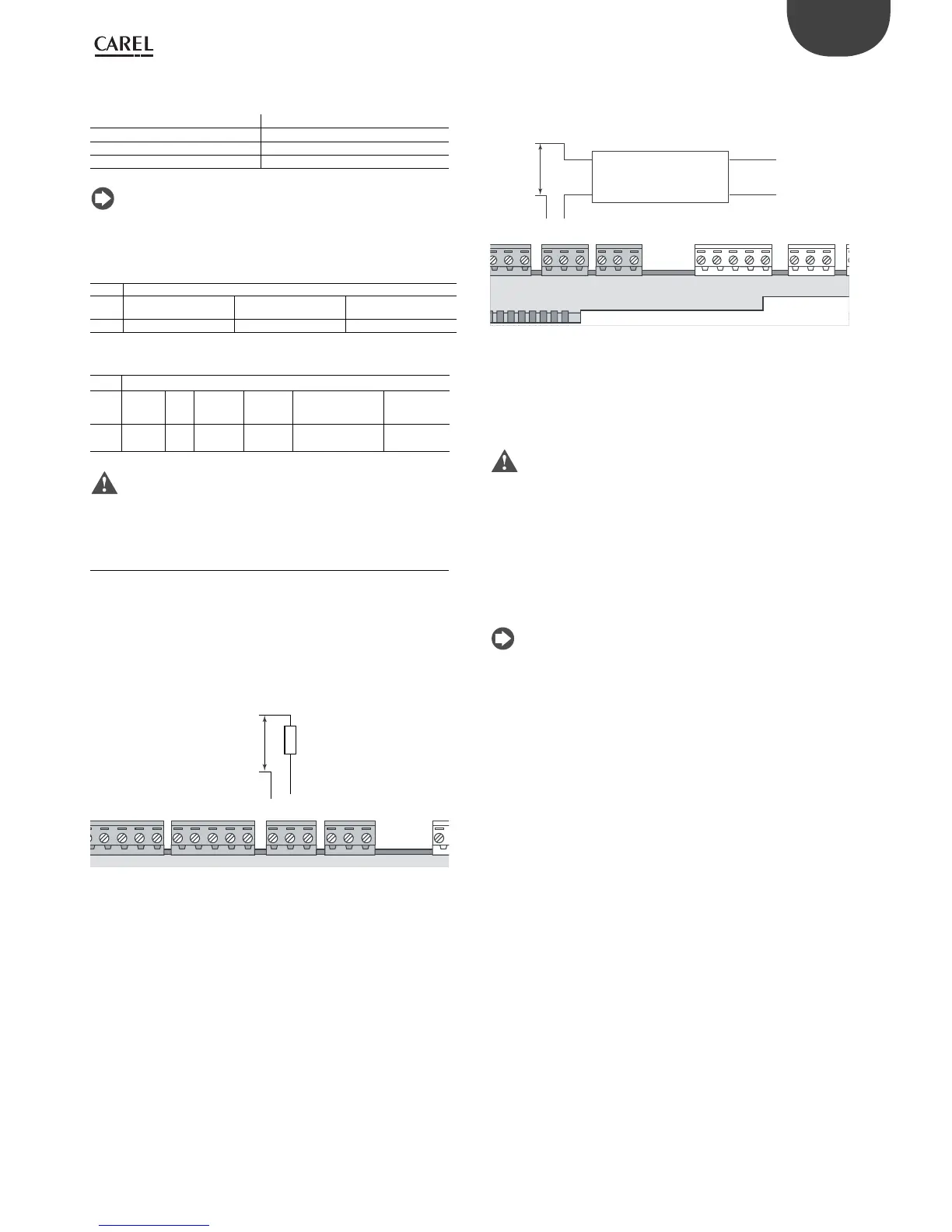
Example 1: connection diagram for resistive load.
NO1
NO2
NO3
C1
C4
NO4
NO5
NO6
C4
C7
NO7
C7
NO8
C8
NC8
24 Vac/Vdc
Fig. 5.ac
Example 2: connection diagram for inductive or resistive loads, with
max. load current < 1 A.
NO5
NO6
C4
C7
NO7
C7
NO8
C8
NC8
24 Vac/Vdc(*)
SSR ESTERNO/
EXTERNAL SSR
carico/load
input
Fig. 5.ad
(*) dedicated power supply or same power supply as controller: not in
common with the power supply for other external loads (e.g. contactors,
coils).
Important: in applications with SSR outputs:
• the controller should only power resistive loads with load current less
than maximum declared;
• use an additional external SSR to power inductive loads;
• for AC power supply to resistive loads or external SSRs, use the same
power supply as the controller (connected to terminals G/G0), which
must be dedicated and not in common with the power supply to other
devices in the electrical panel (contactors, coils, etc.)
Note: the SSR load is powered at 24 Vac SELV, 28 to 36 Vdc SELV or
230 Vac; consequently all the other terminals in the group must be
powered at the same voltage due to the absence of reinforced insulation
within the group.
 Loading...


