36
ENG
c.pCO sistema +0300057EN rel. 1.2 - 29.05.2017
Serial communication and programming
Communication between the c.pCO Medium and its built-in driver
is managed internally through the FBus2 serial port. The FBus2 serial
port (J26) is however electrically isolated from the driver serial line; this
ensures that in case of external faults on the line connected to FBus2,
the internal driver can keep on working independently. The driver can
only be congured using the c.pCO application developed with c.suite;
no external display is available for the driver.
The c.suite development environment features a module for managing
the EVD Evolution driver. When managing the built-in driver, use the
module as if managing an external driver connected to the FBus2 port.
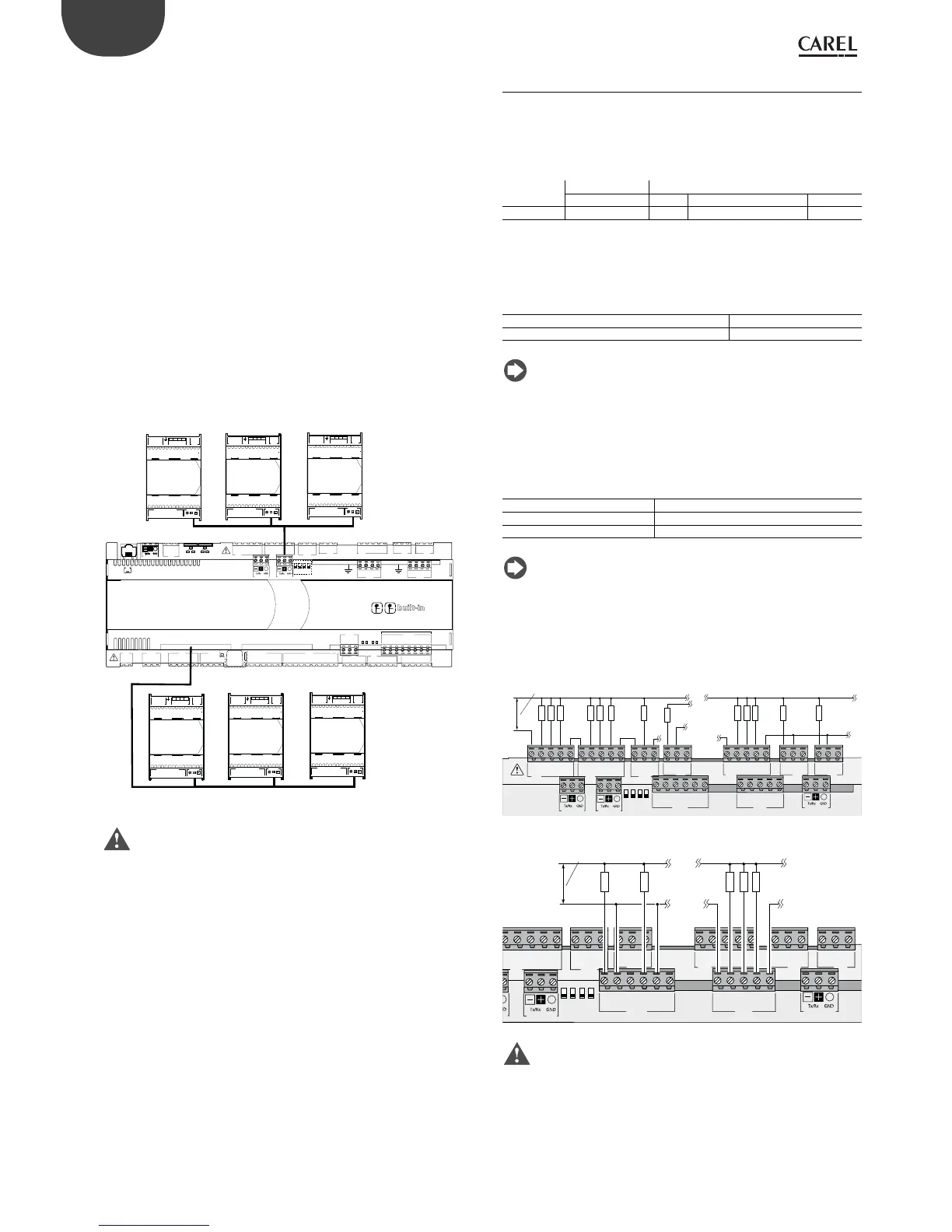
At a c.suite application software level, the valve driver must be connected
to the FBus2 port. Consequently, any other devices physically connected
to the Fbus2 port (J26) must have the same communication protocol
(CAREL Standard Master or Modbus® Master), the same baud rate, stop
bits and parity. The built-in driver address is 198 (EVD Evolution default
address), so any other devices connected to J26 must have an address
other than 198. Communication frame conguration is performed
by using c.suite environment. External EVD Evolution drivers can be
connected to the Fieldbus1 serial port (optional card) with no address
restrictions.
C1
NO1
NO2
A
B
CD
C1
C4
NO4
NO5
NO6
C4
C7
NO7
C7
NO8
C8
NC8
NO12
C12
NC12
NO13
C13
NC13
C9
NO9
NO10
NO11
C9
G
G0
U1
U2
U3
GND
+VDC
+Vterm
GND
+5 VREF
U4
GND
U5
GND
VG
VG0
Y1
Y2
Y3
Y4
ID1
ID2
ID3
ID4
ID5
ID6
ID7
ID8
IDC1
U6
U7
U8
GND
ID9
ID10
ID11
ID12
IDC9
ID13H
ID13
IDC13
ID14
ID14H
FieldBus card
BMS card
CANL
CANH
GND
J26 FBus2
OFF
43 2 1
ON
1
3
2
4
1
3
2
4
driver
VBAT
G0
G
GND
VREF
S1
S2
S3
S4
DI1
DI2
VBAT
G0
G
E
X
V connectionPower Supply Relay
NO 1
COM 1
4231
GND
V REF
S1
S2
S3
S4
DI1
DI2
Analog – Digital Input Network
GND Tx/Rx
VBAT
G0
G
E
X
V connectionPower S upply Relay
NO 1
COM 1
4231
GND
V REF
S1
S2
S3
S4
DI1
DI2
Analog – Digital Input Network
GND Tx/Rx
VBAT
G0
G
E
X
V connectionPower S upply Relay
NO 1
COM 1
4231
GND
V REF
S1
S2
S3
S4
DI1
DI2
Analog – Digital Input Network
GND Tx/Rx
VBAT
G0
G
E
X
V connectionPower Supply Relay
NO 1
COM 1
4231
GND
V REF
S1
S2
S3
S4
DI1
DI2
Analog – Digital Input Network
GND Tx/Rx
VBAT
G0
G
E
X
V connectionPower S upply Relay
NO 1
COM 1
4231
GND
V REF
S1
S2
S3
S4
DI1
DI2
Analog – Digital Input Network
GND Tx/Rx
VBAT
G0
G
E
X
V connectionPower S upply Relay
NO 1
COM 1
4231
GND
V REF
S1
S2
S3
S4
DI1
DI2
Analog – Digital Input Network
GND Tx/Rx
ADDR≠198
ADDR≠198
ADDR≠198
ADDR =198
ADDR =198
Fig. 5.z
Important: to ensure ecient data exchange between the driver
and the controller, when developing the c.suite application, if there are
devices connected to the FBus2 port (terminal J26) using the Modbus®
protocol, developers should take into account the number of variables
exchanged over the entire serial line.
5.7 Digital outputs
Electromechanical relay digital outputs
The controller features digital outputs with electromechanical relays. For
ease of installation, the common terminals of some of the relays have
been grouped together. Some relays feature changeover contacts.
Relays with changeover contacts
c.pCO model
mini - c.pCOe Small Medium / Extralarge Large
Output no. 6 8 8, 12, 13 8, 12, 13
The type of insulation is described in the table below. See also the
Technical Specications table in chap. 12.
c.pCOmini - c.pCOe
Type of insulation
Between relays in group 1 & 2 basic insulation
Between relays in group 3 and in group 1 & 2 reinforced insulation
Note:
• between groups 1 and 2 there is basic insulation, and these must
therefore have the same voltage (generally 24 Vac or 110/230 Vac);
• between the relay groups 1 and 2 and group 3 there is reinforced
insulation, and so group 3 can have a dierent voltage.
c.pCO Small...Extralarge
Type of insulation
Between relays in same group functional insulation
Between groups of relays reinforced insulation
Betw. relays and rest of controller reinforced insulation
Note:
• inside each group, the relays have just functional insulation and must
therefore have the same voltage (generally 24 Vac or 110/230 Vac);
• between groups there is reinforced insulation, so dierent groups can
have dierent voltages.
Example connection diagram (LARGE model):
C1
NO1
NO2
NO3
C1
C4
NO4
NO5
NO6
C4
C7
NO7
C7
NO8
C8
NC8
NO12
C12
NC12
NO13
C13
NC13
C9
NO9
NO10
NO11
C9
J21
J14
J13
J12
J22
J16
J17
J18
J15
NO14
C14
NC14
NO15
C15
NC15
C16
NO16
NO17
NO18
C16
J23 FBus2
J25
BMS2
J26
FBus2
43 2 1
N
L
110/230-24Vac
Fig. 5.aa
 Loading...


