33
ENG
c.pCO sistema +0300057EN rel. 1.2 - 29.05.2017
230 Vac digital inputs (c.pCO Medium...Extralarge only)
Medium and Extralarge models feature one group of 230 Vac inputs
(terminal J8), while Large models have two groups (on terminals J8 and
J19). Each group consists of two digital inputs that can be powered at 230
Vac, indicated as IDH*, and two inputs that can be powered at 24 Vac/Vdc,
indicated as ID*. The two groups of 230 Vac inputs have double insulation
between each other and between them and the controller. The digital
inputs connected may be the 24 Vac/dc inputs from one group and the
230 Vac inputs from the other. The two inputs of each group have the
same common pole. Functional insulation is provided. In each group, the
digital inputs must be powered at the same voltage (24 Vac, 28 to 36
Vdc or 230 Vac) in order to avoid dangerous short-circuits and/or the
risk of powering lower-voltage circuits at 230 Vac
Note:
• the range of uncertainty of the switching threshold is from 43 to 90 Vac;
• the voltage must be 230 Vac (+10/-15%), 50/60 Hz.
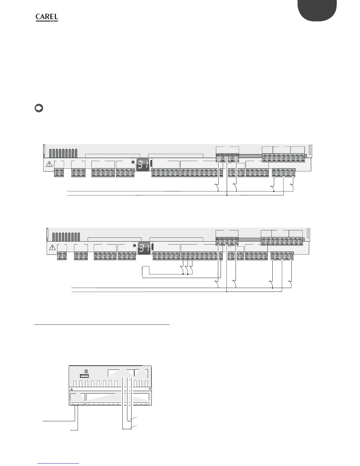
Example 1: connection diagram with 230 Vac inputs.
G
G0
U1
U2
U3
GND
+VDC
+Vterm
GND
+5 VREF
U4
GND
U5
GND
VG
VG0
Y1
Y2
Y3
Y4
ID1
ID2
ID3
ID4
ID5
ID6
ID7
ID8
IDC1
U6
U7
U8
GND
ID9
ID10
ID11
ID12
IDC9
ID13H
ID13
IDC13
ID14
ID14H
J1 J24 J2 J3
J4 J5 J7
J8
J20
J6
J19
ID15H
ID15
IDC15
ID16
ID16H
Y5
Y6
ID17
ID18
IDC17
U9
GND
U10
GND
FieldBus card BMS card
230 Vac
L
N
Fig. 5.r
Example 2: connection diagram with digital inputs at dierent voltages.
G
G0
U1
U2
U3
GND
+VDC
+Vterm
GND
+5 VREF
U4
GND
U5
GND
VG
VG0
Y1
Y2
Y3
Y4
ID1
ID2
ID3
ID4
ID5
ID6
ID7
ID8
IDC1
U6
U7
U8
GND
ID9
ID10
ID11
ID12
IDC9
ID13H
ID13
IDC13
ID14
ID14H
J1
J24 J2 J3
J4 J5 J7
J8
J20
J6
J19
ID15H
ID15
IDC15
ID16
ID16H
Y5
Y6
ID17
ID18
IDC17
U9
GND
U10
GND
FieldBus card BMS card
230 Vac
L
N
-
+
24 Vdc
Fig. 5.s
5.4 Analogue outputs
c.pCOmini: analogue outputs without optical isolation
The controller features 0 to 10 Vdc and PWM analogue outputs without
optical isolation, powered directly by the controller. See the table of the
technical specications (output current, output impedance, etc., Chap. 12).
Example connection diagram (c.pCOmini model):
U1
U2
U3
GND
U4
U5
U6
GND
U7
U8
U9
U10
GND
J1
J2
G
G0
Vbat
+5VREF
GND
+V DC
J9
Y1
GND
ID2
ID1
Y2
GND
J8
J7
24 Vac / 28...36 Vdc
0 V
Vout
Vout
Fig. 5.t
 Loading...


