J1
J24 J2 J3
J4 J5
FieldBus card BMS card
Fig. 6.d
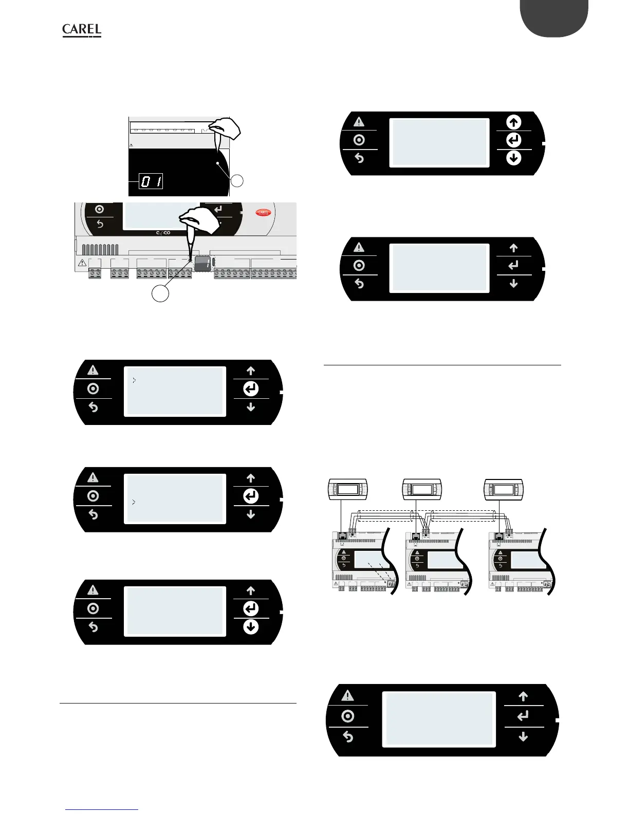
Procedure 2 - system menu
1. press Alarm and Enter together for 3 s and enter the system menu. Select
settings;
INFORMATION
SETTINGS
APPLICATION
UPGRADE
LOGGER
DIAGNOSTICS
2. select pLAN settings;
PASSWORD
USB SETTINGS
PLAN SETTINGS
CLOCK SETTINGS
TCP/IP SETTINGS
3. modify the controller pLAN address and conrm by selecting "Update
conguration".
pLAN pCO Addr:7
Release Term:No
Acquire Term:No
Update config:yes
6.4 Setting the terminal address and connec ting
the controller to the terminal
After setting the controller network address (see previous paragraph),
to establish connections between the controller and the terminal, the
terminal address needs to be set. If the controller is connected to an
external terminal with address 32 (default setting), communication
is established (if the built-in terminal is present, the external terminal
replicates the same visualization). To congure multiple terminals, private
and/or shared, dierent addresses need to be assigned to the terminals,
and the controller must be properly congured:
1. To congure the address of the terminal, press the UP, DOWN and Enter
buttons together for 3 seconds. The screen is displayed in Fig 6.e.
Modify the address of the terminal (in the range 1 to 32) and conrm
by pressing Enter.
Display address
setting........... 32
I/O Board Address: 01
2. A screen is displayed showing the list of the terminals congured.
Set the terminals as private (Priv) or shared (Shared) according to the
application, and conrm to exit. After a few seconds, the connection
will be established.
P:01 Adr Priv/Shared
Trm1 21 Sh
Trm2 22 Sh
Trm3 23 Sh OK?Yes
3. To add a second terminal, repeat the previous steps.
6.5 Sharing terminals in a pLAN network
Once connected in a network (pLAN), the c.pCO controllers can share
the same pGD terminal. A shared terminal may be needed, for example,
to install an update to the operating system and/or application program.
Connect the controllers and terminals to the network (Figure 6.g). Set
the pLAN address for each controller using the dedicated button (see
paragraph 6.3), and for each terminal using the corresponding procedure).
The gure below represents three c.pCO controllers in a pLAN network
with three pGD displays, each with their own address.
Term 1
Addr: 21
Term 2
Addr: 22
Term 3
Addr: 23
c.pCO
Addr:1
c.pCO
Addr: 3
G
G0
U1
U2
U3
GND
+VDC
+V
term
GND
+5 V
REF
U4
GND
U5
GND
J1 J24 J2 J3
J10
FieldBus card
J11 pLAN
G
G0
U1
U2
U3
GND
+VDC
+V
term
GND
+5 V
REF
U4
GND
U5
GND
J1 J24 J2 J3
J10
FieldBus card
J11 pLAN
G
G0
U1
U2
U3
GND
+VDC
+V
term
GND
+5 V
REF
U4
GND
U5
GND
J1 J24 J2 J3
J10
FieldBus card
J11 pLAN
c.pCO
Addr: 2
A
B
Fig. 6.e
1. To set the address on each terminal (Term1, Term2, Term3), see par. 6.4.
2. Enter the address of the three terminals and set them as “shared”. This
operation should be repeated for each of the three terminals (see
paragraph 6.4).
P:01 Adr Priv/Shared
Trm1 21 Sh
Trm2 22 Sh
Trm3 23 Sh OK?Yes
 Loading...


