11
SER VICE TEST
The Service Test function can be use d to verify proper ope ration of
com pressors, hea t ing stages, indoor f an, outdoor fa ns,
Humidi--MiZe r
R
system oper ation, power exhaust fans, ec onomizer,
crankcase heaters, and the alarm relay . Use of Service T est is
recommended at initial system start up and during trouble shooting.
(See Ta ble 4 for point details)
Service Te st mode has the following changes from norma l operati on:
S Outdoor air temperature limits for cooling circuits, economizer,
and heating are ignored.
S Normal compressor time guards and other staging delays are
reduced to one minute or less.
S Cir cuit s t rike out ti me is reduced to 1 minut e instead of 15 mi nut es.
S It may t ake up to 30 seconds to act ually e nter test mode after
activating the command.
Press the TEST button on the SystemVut interface anytime to
access the Test menu. Service Test mode can only be turned
ON/OFF at the unit display. Once turned ON, other entries may be
made with the display or through CCN. To turn Service Test mode
on, change the value of TEST MODE to ON. To turn service test
mode off, change the value of TEST MODE to OFF. Service Test
mode will be automatically turned off based on keypad inactivity
and the Service Mode Test Time out (TEST MODE TIMEOUT).
NOTE: Service Test mode may be password protected. Refer to
Basic Control Usage section for more information. Depending on
the unit model, factory--installed options, and field-- installed
accessories, some of the Service Test functions may not apply.
Independent Outputs
The INDEPENDENTS submenu is used to change output status for
the ec onom izer, Humidi--MiZ er system val ves, power exhaust stages,
crankcase heaters, the alarm relay, as well as perform a compressor
bump test. These independent output s can operate si m ultaneously with
other Service Te st mode s . Al l outputs ret urn to norma l ope rati on when
Service Te st is turned of f. The compr ess or bump tests cannot be run
while r unni ng cooling tests and wi ll automat i cally turn off after one
mi nut e.
Fan Test
The FAN TESTS submenu is used to change speed for the indoor
fan and outdoor fans. The outdoor fan speeds can be controlled
individual or all together with the ALL ODF SPD TEST.The
outdoor fan and indoor fan transition type points inform the test
routine how to handle the fans while running the cooling or
heating tests. Automatic will automatically transition the fans as the
cooling or heating tests change. While the Manual transition will
only run the fans as set by the test points.
Cooling Test
The COOL submenu is used to change output status for the
individual compressors and Humidi--MiZer system operation. The
HEAT submenu service test outputs are reset to OFF for the
cooling service test. Indoor fans and outdoor fans are controlled
normally to maintain proper unit operation when set for automatic
transition. The IDF SPEED TEST and ALL ODFSPD TEST can
be changed as needed for testing. These fans points show the
requested speed not actual speed. All normal cooling faults and
alerts are functional.
Heating Test
The HEAT submenu is used to change output status for the
individual heat stages, gas or electric. The COOL service test
outputs are reset to OFF for the heating service test. Indoor fan is
controlled normally to maintain proper unit operation when set for
automatic transition. The IDF SPEED TEST can be changed as
needed for testing and shows the requested speed not actual speed.
All normal heating faults and alerts are functional.
NOTE: When the IGC fan on command (IGC FAN REQUEST)
is active the fan may run when not expected.
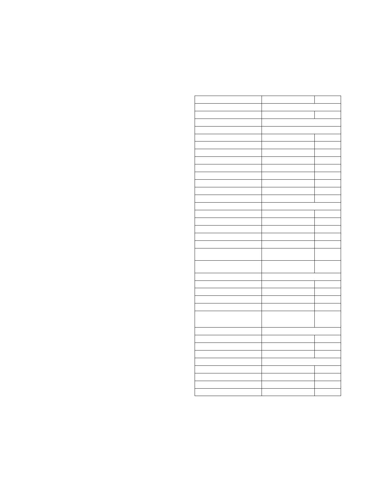
Table 4 – Test Mode Unit Test Directory
Display Menu / Sub Menu / Name Ex pa n de d Na me Values
UNIT TESTS Unit Tests Menu
TEST MODE ServiceTestModeEnable Off/On
SERVICE TEST Serv ice Test Men u
IN DEP ENDEN T S INDEPENDENT TEST MENU
ECON POS TEST Ec on omi zer P os iti on Test 0 to 100
BUMP COMP A1 TEST Compressor Bump A1 Test Off/On
BUMP COMP A2 TEST Compressor Bump A2 Test Off/On
LIQ DIVERT A TEST Liquid Divert A Test Off/On
REHEA T A TE ST Reheat A Test Off/On
CCH RELA Y 1 TEST C rankcase Heater 1 test Off/On
ALARM RELAY TEST Alar m Outpu t Relay Test Off/On
PE1 RELAY TEST Power Exhaust 1 T est Off/On
PE2 RELAY TEST Power Exhaust 2 T est Off/On
FAN TESTS Ind oor and Outdoor Fan tests
IDF SPEED TEST Ind oor Fan Speed Test 0 to 100
ALL ODF SPD TEST S ystem ODF sp eed test 0 to 2000
ODF 1 SPEED TEST Outd oor Fan 1 speed test 0 to 2000
ODF 2 SPEED TEST Outd oor Fan 2 speed test 0 to 2000
ODF 3 SPEED TEST Outd oor Fan 3 speed test 0 to 2000
IDF TRAN S ITION IDF Test T rans ition Type Au tom ati c /
Manual
ODF TRA NS ITION ODF Test T rans ition Type Au tom ati c /
Manual
COOL Cool ing Statu s Me n u
COOL A1 TE ST Cooli n g W/C om p. A 1 Test Off/On
COOL A2 TE ST Cooli n g W/C om p. A 2 Test Off/On
IDF SPEED TEST Ind oor Fan Speed Test 0 to 100
ALL ODF SPD TEST S ystem ODF sp eed test 0 to 2000
HUMIDIMIZER TEST H u m i d i --- M i Z e r
R
system test 0=off
1 = Su b cool
2=Reheat
HEAT Heatin g Status Me n u
HEAT 1 TEST Heating Stag e 1 Test Off/On
HEAT 2 TEST Heating Stag e 2 Test Off/On
IDF SPEED TEST Ind oor Fan Speed Test 0 to 100
AUTOMATIC TEST Au tom ati c Test Menu
AUTO INDP TEST AUTO INDEPENDENT TEST Yes/No
AUTO COOL TEST RUN AUTO COOLING TEST Yes/No
AUTO HEAT TEST RUN AUTO HEATING TEST Yes/No
AUTO SYSTEM TEST RUN AUTO SYST EM TES T Yes/No
 Loading...