61
Variable Frequency Drive (VFD)
VFDs are available as a factory-- installed option for LC series
units. Size 04 -- 06 units use ABB VFDs while sizes 07-- 26 use
Danfoss VFDs. For details on size 07 -- 26 units with VFDs
continue at page 65.
LC 04--06 Variable Frequency Drive (ABB VFD)
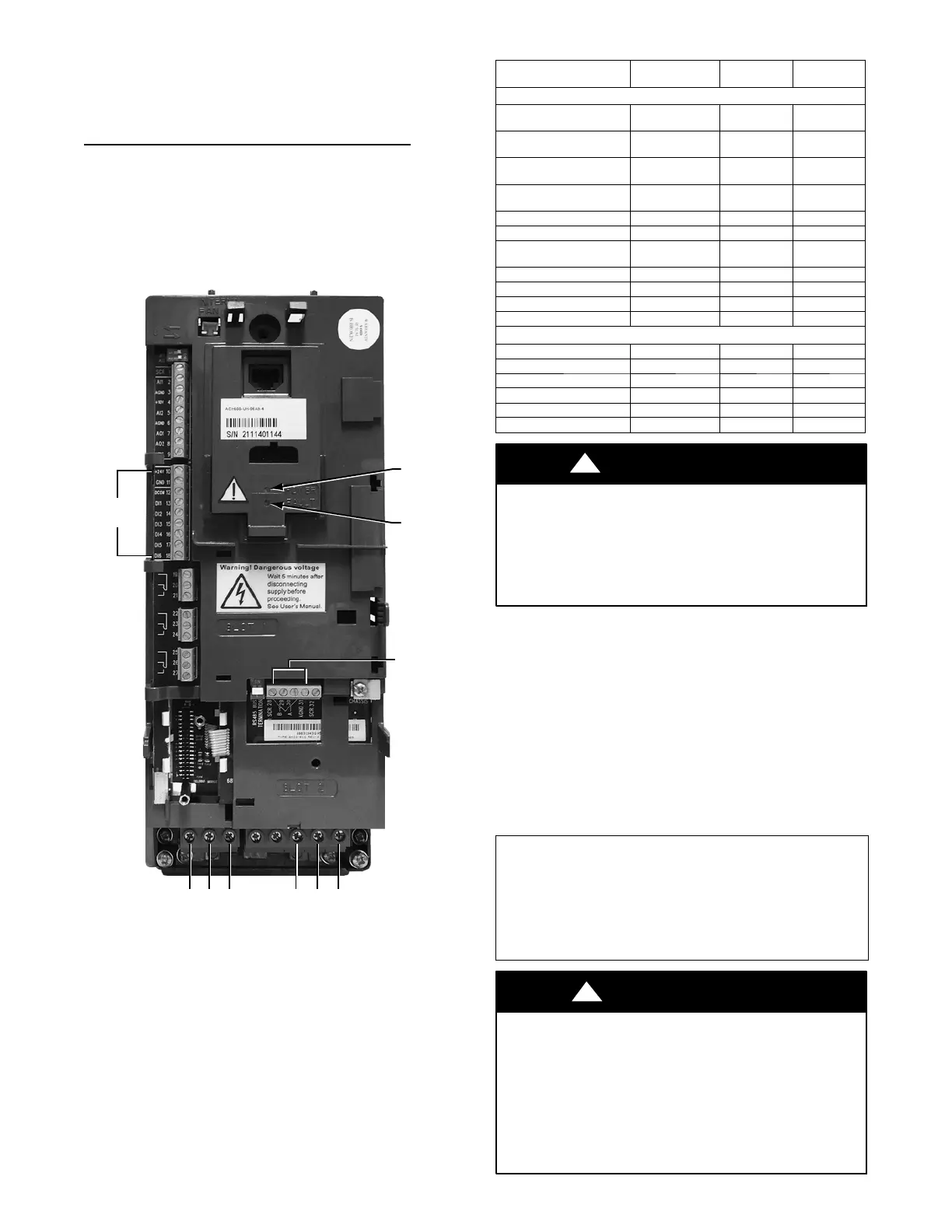
On units equipped with supply fan VFDs, the indoor fan motor is
controlled by a 3-phase VFD. The supply fan VFD is located in the
supply fan section behind the access door. These units use ABB
VFDs. The VFD varies the frequency of the AC voltage supplied
to the indoor fan. This allows the variance in the speed of the fan.
The VFD is always powered during normal operation and the fan
is stopped by driving the speed to 0. Fig. 37 and Table 27 show the
VFD terminals and connections.
TERMINALS
10 – 16
TERMINALS
28 – 31
U1 V1 W1 U2 V2 W2
POWER
LED
FAULT
LED
C12225
Fig. 37 -- LC 04-- 06 Va riable Frequency Drive (VFD) Termin-
als and Connections -- unit shown front cover removed
The VFD is factory–configured to match the current and power
requirements for each motor selection and all wiring connections
are completed by the factory; no field adjustments or connections
are necessary. While the basic VFD retains all of its standard
capabilities, this application uses only a limited portion of these
features to provide discrete output speeds to the motor.
Consequently the VFD is not equipped with a keypad. A keypad is
available as an accessory (P/N: CRDISKIT001A00) for field
installation or expanded service access to VFD parameter and
troubleshooting tables. The VFD used has soft start capabilities to
slowly ramp up the speeds, eliminating any high inrush of air
volume during speed changes.
Table 27 – LC 04-- 06 VFD Connections
POINT DESCRIPTION TYPE OF I/O
TERMINAL
NUMBER
TERMINAL
NAME
LOW VOLTAGE INPUTS
Low Voltage Power
(jumped to DI1 & DI4)
24vdc 10 24v
Low Voltage Common
(jumped to DCOM)
Ground 11 GND
Discrete Inputs Common
(jumped from GND)
Ground 12 DCOM
Discrete Input 1
(jumped from 24v)
Switch Input 13 DI1
Not Used Switch Input 14 DI2
Not Used Switch Input 15 DI3
Discrete Input 4
(jumped from 24v)
Switch Input 16 DI4
Shielded Cable Ground Shield 28 SCR
LEN communication LEN 29 B+
LEN communication LEN 30 A ---
LEN Communication LEN 31 AGND
HIGH VOLTAGE
Vo l t a g e L e g f r o m C --- 1 1 V oltage Input U1 MAINS
Vo l t a g e L e g f r o m C --- 1 3 V oltage Input V1 MAINS
Voltage Leg from IFTB Voltage Input W1 MAINS
Vo l t a g e L e g t o I F M --- 3 Voltage Output U2 MOTOR
Vo l t a g e L e g t o I F M --- 2 Voltage Output V2 MOTOR
Vo l t a g e L e g t o I F M --- 1 Voltage Output W2 MOTOR
EQUIPMENT DAMAGE/PERFORMANCE HAZARD
Failure to follow this caution may result in damage to the unit
or in degradation of unit performance.
Do not run the Carrier Assistant through the VFD keypad.
This will cause parameters to change value that are not desired
on these applications.
CAUTION
!
The VFDs communicate to the MBB over the local equipment
network (LEN). The VFD speed is controlled directly by the
SystemVut controller over the LEN. The VFD parameters
required to allow the VFD to communicate on the LEN are shown
in Table 28. Table 29 shows VFD parameters that are hard--coded
by the SystemVu controller . The parameters listed in Table 30 have
corresponding SystemVu configurations (SETTINGS UNIT
CONFIGURATIONS INDOOR FAN IFD VFD
PARAMETERS). The factory sets these parameters per motor
installed in the unit and these should not be adjusted in the field.
These are only provided for drive or motor replacement. These
parameters in Table 30 require the drive to be off or 0% to change
them.
IMPORTANT : If the VFD appears to be communi cati ng (t he VFD
software version can be read in SERVIC E UNIT
INFORMATION VERSIONS) but the loss of com m uni cations
fault per sists, pla ce the keypad in the Of f state. If communica t ion is
reestablished the VFD had to be in the Off state to save the
configurations be ing s ent.
This can occur after a VFD is replaced.
EQUIPMENT DAMAGE HAZARD
Failure to follow this warning could result in equipment
damage.
The VFD motor parameters shown in Table 32 should never be
changed in the field unless authorized by Carrier Corporation.
Damage could occur to the motor or unit if these are set to
anything besides what is shown in the table. These are only
provided for drive or motor replacement or future adjustments.
!
WARNING
 Loading...