74
Table41—LC--7--26VFDFaultCodes(cont)
SystemVu Faul t SystemVu Alert
VFD
Number
VFD Description
VFD
Warning
VFD
Alarm
Trip
Lock
Cause of Problem
F601--- IDF VFD
UNEXPECTED
A608--- IDF VFD WARNING 95 Broken Belt X X
Torque is below the torque level set for no load,
indicating a broken belt.
F601--- IDF VFD
UNEXPECTED
--- 38 Internal fault X X Contact your local Carrier represent ative.
F601--- IDF VFD
UNEXPECTED
--- 50
AMA Calibration
Failed
X Contact your local Carrier representative.
F601--- IDF VFD
UNEXPECTED
--- 51
AMA check Unom
and Inom
X
The setting of motor voltage, motor current and motor
power is presumably wrong. Check the settings.
F601--- IDF VFD
UNEXPECTED
--- 52 AMA low Inom X The motor current is too low. Check the settings.
F601--- IDF VFD
UNEXPECTED
--- 53 AMA motor too big X The motor is too big for t he AMA to be carried out.
F601--- IDF VFD
UNEXPECTED
--- 54
AMA motor too
small
X The motor is too small for the AMA to be carried out.
F601--- IDF VFD
UNEXPECTED
--- 55
AMA Parameter out
of range
X
The parameter values found from the motor are outside
acceptable range.
F601--- IDF VFD
UNEXPECTED
--- 56
AMA interrupted by
user
X The AMA has been int errupted by the user.
F601--- IDF VFD
UNEXPECTED
--- 57 AMA timeout X
Try to start the AMA again a number of times, until the
AMA is carried out. Please note that repeated runs may
heat the motor to a level where the resistance Rs and Rr
areincreased.Inmostcases,however,thisisnotcritical.
F601--- IDF VFD
UNEXPECTED
--- 60 External Interlock X
External interlock has been activated. To resume normal
operation, apply 24 V DC to the terminal programmed for
external interlock and reset the variable fre quency drive
by pressing the Off/Reset button on the keypad.
F601--- IDF VFD
UNEXPECTED
--- 80
Drive Initialized to
Default Value
X All parameter setting are initialized to default settings.
F601--- IDF VFD
UNEXPECTED
--- 250 New spare parts X X
The power or switch mode power supply has been
exchanged. (Only on 400 V 30 to 90 kW units). Contact
your local Carrier representative.
F601--- IDF VFD
UNEXPECTED
--- 251 New Type Code X X
The variable frequency drive has a new type of code
(Only on 400 V 30 to 90 kW units). Contact your local
Carrier representative.
Carrier Comfort Network
R
(CCN) Interface
The units can be connected to the CCN if desired. The
communication bus wiring is a shielded, 3-conductor cable with
drain wire and is field supplied and installed. The system elements
are connected to the communication bus in a daisy chain
arrangement. (See Fig. 39.) The positive pin of each system
element communication connector must be wired to the positive
pins of the system elements on either side of it. This is also
required for the negative and signal ground pins of each system
element. Wiring connections for CCN should be made at the CIB.
(See Fig. 27 and 28.) Consult the CCN Contractor’s Manual for
further information.
NOTE: Conductors and drain wire must be 20 AWG (American
Wire Gauge) minimum stranded, tinned copper. Individual
conductors must be insulated with PVC, PVC/nylon, vinyl,
Teflon*, or polyethylene. An aluminum/polyester 100% foil shield
and an outer jacket of PVC, PVC/nylon, chrome vinyl, or Teflon
with a minimum operating temperature range of –20_Cto60_Cis
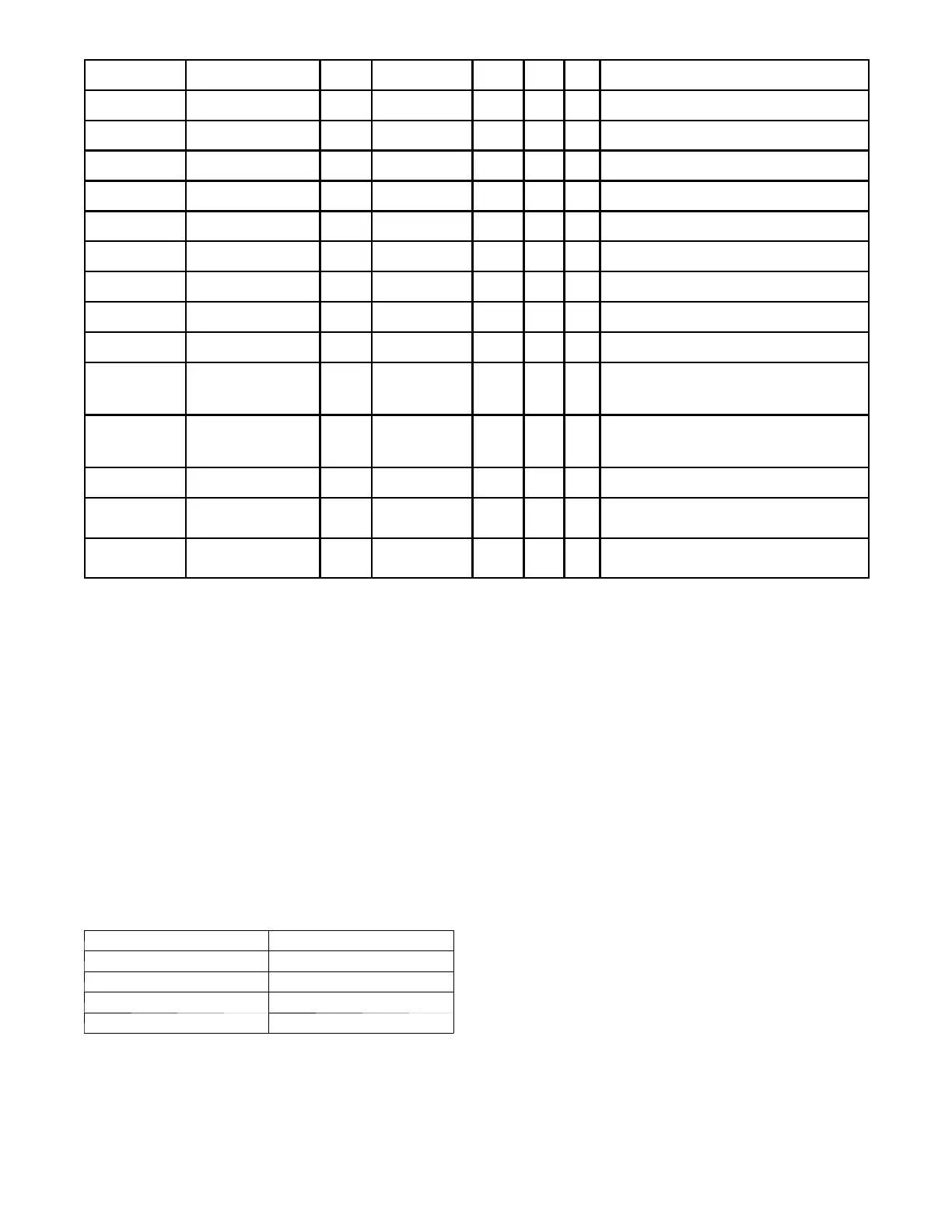
required. See Table below for acceptable wiring.
MANUFACTUR ER PART NO.
Alpha 2413 or 5463
Belden 8772
Carol C2528
West Penn 302
It is important when connecting to a CCN communication bus that
a color-coding scheme be used for the entire network to simplify
the installation. It is recommended that red be used for the signal
positive, black for the signal negative and white for the signal
ground. Use a similar scheme for cables containing different
colored wires.
*Teflon is a registered trademark of DuPont.
At each system element, the shields of its communication bus
cables must be tied together. The shield screw on CIB can be used
to tie the cables together . If the communication bus is entirely
within one building, the resulting continuous shield must be
connected to a ground at one point only. The shield screw on CIB
is not acceptable for grounding. If the communication bus cable
exits from one building and enters another, the shields must be
connected to grounds at the lightning suppressor in each building
where the cable enters or exits the building (one point per building
only).
To connect the unit to the network:
1. Turn off power to the control box.
2. Cut the CCN wire and strip the ends of the red (+), white
(ground), and black (–) conductors. (Substitute appropriate
colors for different colored cables.)
3. Connect the red wire to (+) terminal on CIB, the white wire
to COM terminal, and the black wire to the (–) terminal.
4. The RJ14 CCN connector on CIB can also be used, but is
only intended for temporary connection (for example, a
laptop computer running Carrier network software).
5. Restore power to unit.
IMPORTANT: A shorted CCN bus cable will prevent some
routines from running and may prevent the unit from starting. If
abnormal conditions occur, unplug the connector. If conditions
return to normal, check the CCN connector and cable. Run new
cable if necessary. A short in one section of the bus can cause
problems with all system elements on the bus.
 Loading...