12
Automatic Test
The AUTOMATIC TEST sub m enu is used to ex ecute all the
app licable tests to t h e system au tom atically. Th ese in clu d e
independent component, cooling, heating, and a system one.
Table 5 shows the steps taken during the independent, cooling,
and heatin g auto m atic tests. T h e Ho l d tim e rep resen ts th e time at
which that control waits before moving on to the next step.
The AUTO SYSTEM TEST will execute the independent auto
test, then the cooling auto test, then the heating auto test. At the end
of the system auto test a prompt will ask if you want to enter
measured data and complete a service report.
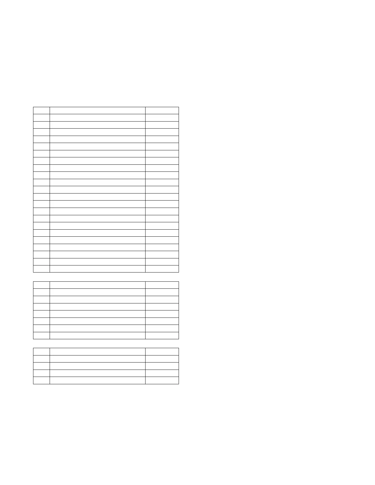
Table 5 – Independent, Cooling, and Heating Automatic Tests
AUTO INDP TEST
Step Action Hold (Sec)
1 Turn on Crankcase Heater Relay 0
2 Set ODF1 to the High Cool Speed 30
3 Set ODF1 to the Minimum Speed 30
4 Tur n ODF1 of f 5
5 Set ODF2 to the High Cool Speed 30
6 Set ODF2 to the Minimum Speed 30
7 Tur n OD21 of f 5
8 Set ODF3 to the High Cool Speed 30
9 Set ODF3 to the Minimum Speed 30
10 Tu rn OD F3 off 5
11 Se t IDF speed to 100% 30
12 Se t Economizer Dam per to 100% 60
13 Tu rn o n power e xhaust 1 10
14 Tu rn o n power e xhaust 2 10
15 SetEconomizerDamperto0% 60
16 Tu r n off power exhaust 2 10
17 Tu r n off power exhaust 1 10
18 Set IDF to the ventilation speed 30
19 Turn on al arm relay 10
20 Turn off alarm relay 10
21 Set IDF to 0% speed 30
22 Turn off Crankcase Heater relay 0
AUTO COOL TEST
Step Action Hold (Sec)
1 Set ODF auto transition 0
2 Set IDF auto transition 0
3 Turn on Cool A1 test 60
4 Turn off Cool A1 test 30
5 Turn on Cool A2 test 60
6 Turn on Cool A1 and Cool A2 tests 30
7 Turn off Cool A1 and Cool A2 tests 60
AUTO HEAT TEST
Step Action Hold (Sec)
1 Set IDF auto transition 0
2 Tur n on He at 1 te st 60
3 Tur n on He at 2 te st 60
4 TurnoffHeat1andHeat2tests 20
THIRD PARTY CONTROL
Third party controls may interface with the unit SystemVut
controller through the connections described below. See other
sections of these instructions for more information on the related
unit control and configurations.
Cooling/Heating Control
The thermostat inputs are provided on TB1 of the board. The
Unit Control Type configuration, UNIT CONTROL TYPE,
must be 0 (Tstat) to recognize the below inputs. Terminal R is
the 24 -- VAC source for the following:
Y1 = first stage cooling
Y2 = second stage cooling
Y3 = third stage cooling
W1 = first stage heating
W2 = second stage heating
G = Indoor fan
Dehumidification Control
On Humidi--MiZer
R
system units the HUMIDIST AT and SPRH leads
are provi ded with quick connects. The Space Humidi ty Switch
configuration, SETTINGSUNIT CONFIGURATIONS
SWITCH INPUTS CONFIGSHUMSTA T CHANNEL
identifi es the norm ally open or normally closed sta tus of this input at
HIG H humidity. The RH Sensor conf i gurati on, SETTINGS UNIT
CONFIGURATIONSANALOG INPUTS CONFIGS SPRH
SENSOR CHANNEL, ident ifies the point on t he MBB (Main Bas e
board) or t he IOB (Input Output board) the sensor was wir ed into.
Remote Occupancy
The remote occupancy input can be provided on one of the
configurab le inputs, most commonly TB3. The Remote
Occupancy Switch configuration, REMOTE OCC TYPE,
identifies the normally open or normally closed status of this input
when unoccupied. The Remote Occupancy Channel configuration,
REMOTE OCC CHAN, identifies the discrete input (DI) assigned
for this function.
Remote Shutdown
The re m ote shut dow n input is pr ovi ded for unit shutdown in re sponse
to swi t ch input configured most com monly on TB3. The Remote
Shutdown Switch c onfiguration, REM. SHUTDOWN TYPE,
identifi es the norm ally ope n or nor mally closed status of this i nput
whe n there is no shutdow n command. The Remot e Shutdown
Channel c onf iguration, REM. SHUTDOWN CHAN, identifies the
discrete input (DI) assigned for t hi s function.
Alarm Output
The alarm output is provided on as a configurable relay, most
commonly on TB2, to indicate when a current alarm is active. The
output will be 24-- VAC if a current alarm exists. The Alarm Relay
Channel configuration, ALM RELY CHANNEL, identifies the
discrete output (DO) assigned for this function.
Economizer Damper Control
For units with the economizer option or accessory, the damper
position can be directly controlled through the IAQ sensor input.
The IAQ Analog Input configuration, IAQ LEVEL CONTROL
will have to set to 2 (CTL MINP). When IA.CF = 2, an external 4
to 20 mA source is used to move the damper 0% to 100% directly.
CONTROLS OPERATION
Display Configuration
The SETTINGSDISPLAY S ETTINGS submenu is used to
configure the local display settings.
METRIC DISPLAY
This variable is used to change the display from English units to
Metric units.
LANGUAGE
This variable is used to change the language of the SystemVu
display. At this time, only English is available.
CONTRAST ADJUST
This is used to adjust the contrast of the SystemVu display.
 Loading...