13
PASSWORD ENABLE?
This va riabl e enables or disables the us e of a use r password. The
passwor d is us ed to re stric t use of the control to c hange conf igurations.
VIEW USER PASSWORD
This menu allows the user to view the user password. The
password must be entered or disabled to view it.
CHANGE USER PASSWORD
This menu allows the user to change the user password. The
password must be entered or disabled to change it.
Unit Configuration
Many configurations that indicate what factory options and/or field
accessories are installed and other common operation variables are
included in SETTINGSUNIT CONFIGURATION submenu.
Some of these configurations will be set in the factory for the
factory--installed options (FIOPs). Field installed accessories and
custom control functions will require configuration changes. The
SETTINGSUNIT C ONFIGURATIONGENERAL submenu
contains the following control configurations. Refer to other
specific sections for other configurations.
STARTUP DELAY
This configuration sets the control start-up delay after the power is
interrupted. This can be used to stagger the start-up of multiple
units.
UNIT CONTROL TYPE
This configuration defines if temperature control is based on
thermostat inputs or space temperature sensor input. TSTAT value
is when then unit determines cooling and heating demand by the
state of G, Y1, Y2, W1, and W2 inputs from a space thermostat.
This value is the factory default. SPACE SEN value is when the
unit determines cooling and heating demand based on the space
temperature and the appropriate set point. RAT SEN value is when
the unit determines cooling and heating demand based on the
return air temperature and the appropriate set point. SPACE SEN
or RAT SEN are also used as Linkage configuration.
THERMOSTAT TYPE
This configuration applies only if Unit Control Type is Thermostat.
The value determines how the inputs are interpreted. See the
specific operation sections for more information. The following
descriptions define what each value means.
0 = CONV 2C2H – Conventional Thermostat 2 stage cool and
2 stage heat.
1 = DI GI 2C2H – Digital Thermostat 2 st age cool and 2 stage heat.
2 = CONV 3C2H – Conventional Thermostat 3 stage cool and
2 stage heat. This is the default setting.
3 = DIGI 3C2H – Digital Thermostat 3 stage cool and 2 stage heat.
ADAPTIVE TSTAT
This configuration applies only if the Unit control type is
Thermostat. When this is YES the control will use Adaptive
Control for cooling and heating staging. When this is set to NO the
control will use the Traditional Thermostat Control, however
during integrated cooling Adaptive is always used.
DIRTY FILTER TIME
This configuration defines the life of the installed filter. A timer
will count down from this number while the indoor fan is running.
At the expiration of this timer, an alert will be activated to indicate
a filter change is required.
TEST MODE TIMEOUT
This configuration defines the time at which a test mode test has
not changed state will automatically disable test mode. This
configuration will disable the timeout when set to 0 (Disabled).
CCH MAX TEMP
This configuration defines the temperature threshold for which the
crankcase heater is no longer required to heat the compressor shell.
STD BARO PRESSURE
This configuration is used to spe cify the job location’s st andar d
barometer pressure reading. This will feed the BAROMETRIC
PRESS when a network is not writing to it. This should be used to
account for job si te ele vation if e nthalpy calculations are bei ng use d.
LINK STAGEUP TIME
This configuration sets the cooling and heating stage up time
during linkage operation.
Configurable Switches and Analog sensors
The Syst emV ut cont roller has opti onal conf i gurable inputs . These
consist of five physi cal boar d switch input s (di screte input s) a nd three
physical board analog input s. There are more functions all ow ed for
configuration than the re are inputs. Eac h func tion will have a
configuration for which input cha nnel it is as signed to. Each switch
function wil l al so have a switch type configuration whi ch defines tha t
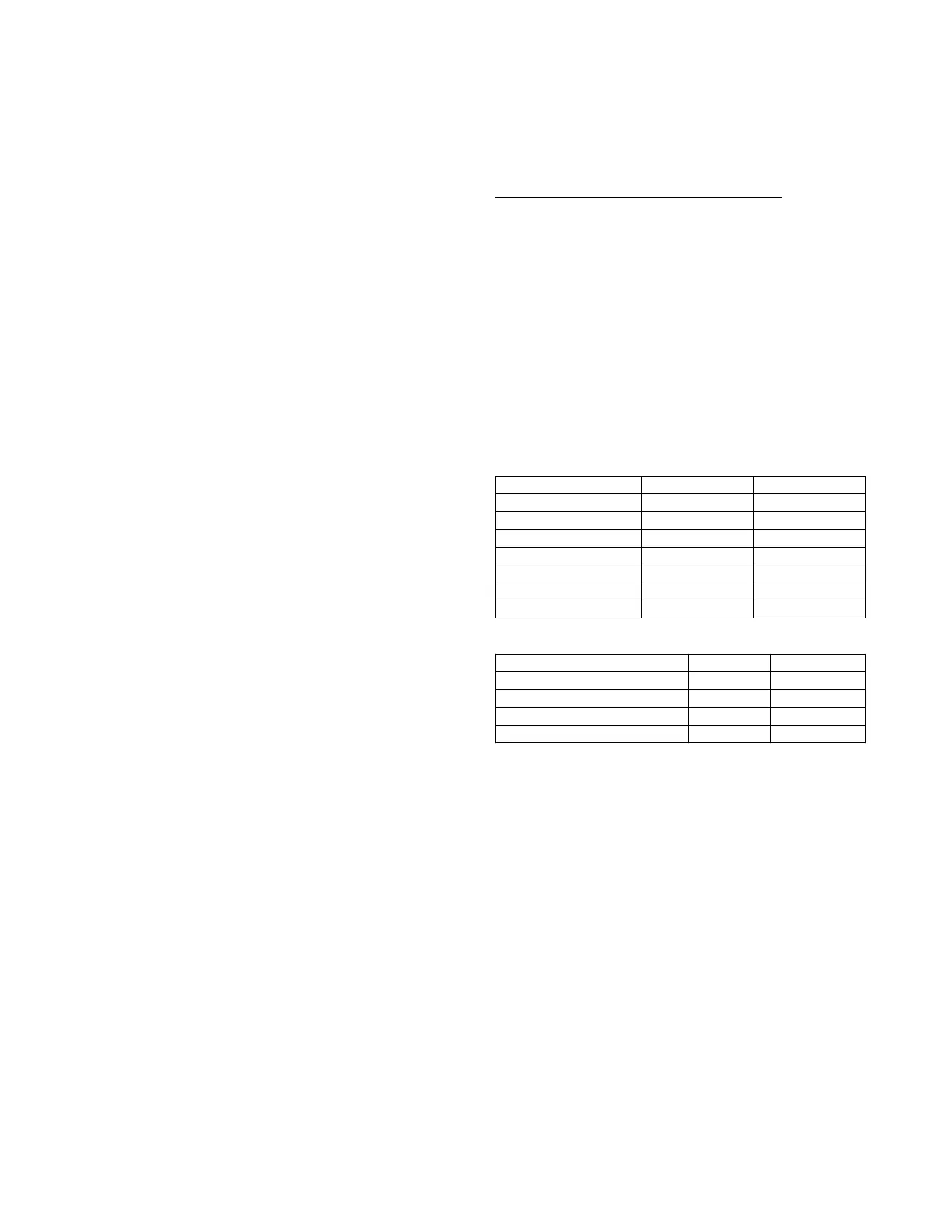
sw i tches norma l st ate. Ta ble 6 shows the conf igurabl e functions and
wha t the ir normal and ac tive states a re. Tabl e 7 shows the configurable
analog input func t ions. The switch conf igurations ca n be found in the
SETTINGSUNIT CONFIGURATIONSSWITCH INPUT
CONFIGS sub--menu. The analog input configurations ca n be found
in the SETTINGUNIT CONFIGURATIONSSWITCH INPUT
CONFIGS sub--menu. The configurabl e input as signment can be
viewed in the SER VI CEHARDWAREASSIGNED
INPUTS/ OUTPUTS sub--menu.
Table 6 – Configurable Switch Input Functions
F unction Description Normal State Active State
Humidistat OFF ON
Condensate Overflow LOW HIGH
Filter Status Switch CLEAN DIRTY
Remote Occupancy UNO CC OCCUP IED
Remote Shutdown RUN SHUTDOWN
General Status Switch GOOD ALARM
Enthalpy Switch Input LOW HIGH
Table 7 – Configura ble Analog Input Functions
F unction Description Sensor Type Sensor Values
Space Air Relative Humidity Sensor 0 --- 2 0mA %RH
Return Air Relative Humidity Sensor 0 --- 2 0 mA %RH
Indoor Air CO
2
Sensor 0 --- 2 0mA PPM
Outside Air CO
2
Sensor 0 --- 2 0m A CFM
General Operation
48/50LC units can provide cooling, dehumidification, heating, and
ventilation. The operating mode (MODE) shows the highest level
of operation of the unit at any given time. The operating sub--mode
(SUB-- MODE) shows the detail operation occurring while under a
specific mode. Fig. 10 shows the MODE and SUB -- MODE values.
Each unit will operate under one of three basic types of control,
thermostat, space temperature sensor, or return air temperature
sensor. There are many inputs, configurations, safety factors, and
conditions that ultimately control the unit. Refer to the specific
operation sections for detail on a specific unit operation. The
control will set the demand based on these types of control and
conditions, which then drives the operating mode.
When thermostat control is enabled (UNIT CONTROL TYPE),
the unit will operate based on discrete input commands (G, Y1,
Y2, Y3, W1, and W2) and there is a one minute time delay
between modes and when re--entering a mode. The G command
calls for ventilation, the Y1, Y2, and Y3 commands call for
cooling, and the W1 & W2 commands call for heating. Thermostat
Contro l Type (THERMOSTAT TYPE) affects how cooling
operates based on Y1, Y2, and Y3 commands and if
cooling/heating stage time guards are applied.
When space temperature sensor control in enabled (UNIT
CONTROL TYPE), the unit will try to maintain the Space
Temperature (SPACE TEMPERATURE) between the effective
 Loading...