9
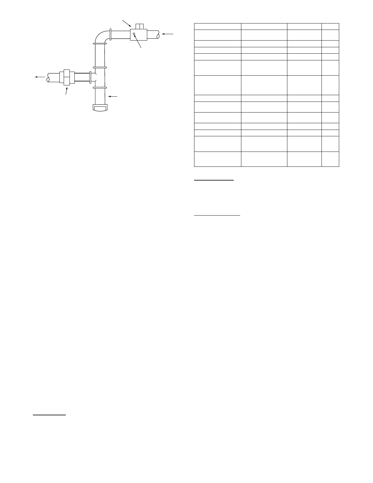
MANUAL GAS SHUT OFF VALVE
(FIELD SUPPLIED)
SUPPLY GAS
PRESSURE TAP
(1/8˝ NPT PLUG)
GAS
SUPPL
SEDIMENT TRAP
UNION
TO
UNIT
a48---9382
Fig. 9 -- Field Gas Piping
3. Connect a pressure gauge to the manifold pressure tap on
the burner assembly located inside the unit.
4. Ope n the field-s upplied manua l gas shut off va l ve. Ente r
Service T est mode by setting TEST MODE to “ON” using the
SystemVut controller interface. Use the Service Test feature
to set HEA T 1 TEST to ON (firs t stage of heat) using the
SystemV u controller interface.
5. After the unit has run for several minutes, verify the supply
gas pressure is adequate per the base unit installation in-
structions. If not, adjust accordingly .
NOTE: Supply gas pressure must not exceed 13.0--in. wg.
6. Set HEAT 1 TES T to OFF using the SystemVu controller
interface.
7. Exit Service Test mode by setting TEST MODE to “OFF”
using the SystemVu controller interface.
CONTROLS QUICK SET--UP
The following information will provide a quick guide to setting up
and conf iguring the 48/50LC series units wi t h Syst emVu control s.
Unit cont r ols are pre - configured a t the fa ctory for factory-installed
options. Field-installed accessories will require configuration at
start-up. Initial System Startup is recommended for initial start--up.
Additionally, specific job re quirem ents may re quire changes to default
configuration val ues. See Appe ndi x A and othe r s ecti ons of these
instructions for mor e det ails . Ref er to the Ma jor System Component s
or accessory installation instructions for specific wiring detail.
Control Set Point and Configuration Log
During start up, accessory installation, and equipment service set
points and/or configuration changes might have to be made. When
setting set points or configuration settings, documentation is
recommend. The Control Set Point and Configuration Log starting
on page 153 should be filled out and left with the unit at all times,
a copy should also be provided to the equipment owner. A USB
jump drive can be used to back up the unit’s configurations. Refer
to the USB Operation section for details.
Initial Startup
Initial Startup refers to the first time this particular unit has a startup
performed. The SystemVu controller will continually display the
Initial Startup prompt until it is completed. To complete the initial
startup you must complete the Quick Setup, Network Setup, and
the System Auto Test.
Quick Setup
This a list of common adjusted configurations set during startup.
These are common accessories, and control means. Set the list in
Table 3. After setting these per the specific unit set the QUICK
SET CHKLIST point to done.
Table 3 – Quick Setup Menu Items
SystemVu™ Display Expanded Name Range Default
QUICK SETUP CONFIG QUICK SETUP
CONFIG MENU
TIME Clock Hour and Minute HH:MM
DATE Current Date MM/DD/YYYY
STARTUP DELAY Unit Startup Delay 10 to 600 30
UNIT CONTROL TYPE Unit Control Type 0=TSTAT,
1=SPACE SEN,
2=RAT SEN
0
THERMOSTAT TYPE Thermostat Hardware
Type
0=CONV 2C2H,
1=DIGI 2C2H,
2=CONV 3C2H,
3=DIGI 3C2H
2
DIRTY FILTER TIME Change Filter Timer 0to9999 600
VENT IDF SPEED Ventilation Only IDF
Speed
0to100 67*
HEATINGSTAGQTY Number of Heating
Stages
1to2 2*
ECON INSTALLED? Economizer Install ed? No/Yes No*
FREECOOL MAX OAT Free Cooling Max OAT 0to90 65
FIRE SHUTDOWN SW Fire Shutdown Switch 0=No Switch,
1=N/Open
2=N/Close
0*
QUICK SET CHKLIST QUICK SETUP
CHECKLIST
0=Undone,
1=View,
2=Done
0
* These defaults change based on the Unit model number.
Network Setup
This is a shortcut to the Network Settings submenu. In this sub
menu are the specific network settings required to get the network
piece up and running. After setting these per the specific unit set
the NETWORK CHKLIST point to done.
System Auto Test
Turning this to Start will run enable test mode and execute the System
Auto Test. Af ter the auto test has completed, set thi s to done .
Thermostat Control
Wire accessory thermostat to the corresponding R, Y1, Y2, Y3,
W1, W2, and G terminals on the Main Base board.
The Unit Control Type configuration, (UNIT CONTROL TYPE)
default value is for thermostat (0) so there is no need to configure
this item.
The Thermostat Hardware Type, (THERMOSTAT TYPE) selects
the unit response to the thermostat inputs above.
NOTE: May not be compatible with heat anticipator thermostats.
Space Temperature Sensor Control -- Direct Wired
(T--55 or T--56 or T--59)
Wire accessory space temperature sensor(s) to the T-55 terminals
on the field connection terminal board located at the unit control
box. Refer to Space Mounted Sensors sectio n (page 59) for
additional information.
The Unit Control Type configuration, (UNIT CONTROL TYPE)
must be set to Space Sensor (1).
Space Humidistat Control
For units with the factory--installed Humidi--MiZer
R
system
option, the humidistat input is provided with quick connects. The
Space Humidity Switch configuration, SETTINGS UNIT
CONFIGURATIONS SWITCH INPUTS CONFIGS
HUMSTAT CHANNEL identifies the normally open or normally
closed status of this input at HIGH humidity.
Relative Humidity Sensor Control
For units with the factory--installed Humidi--MiZer system option,
the humidity sensor input is provided with quick connects. The
sensor can be used instead of a humidistat. The RH Sensor
configuration, SETTINGS UNIT CONFIGURATIONS
ANALOG INPUTS CONFIGS SPRH SENSOR CHANNEL,
identifies the point on the MBB (Main Base board) or the IOB
(Input Output board) the sensor was wired into.
 Loading...