15
Table 10 – Thermostat Heating System Demands
Thermostat Input THERMOSTAT TYPE
W1 W2
CONV 2C2H
CONV 3C2H
DIGI 2C2H
DIGI 3C2H
0 0 No Heat No Heat
0 1 Alert & Low Heat High Hea t
1 0 Low Heat Low Heat
1 1 High Heat High Heat
Space Sensor Demand
When the unit control type is configured for space sensor (UNIT
CONTROL TYPE = S PACE SEN) the level 5 demand in Table 8
will be determined by the space sensor inputs and setpoints as
described below. The Effective Demand Temperature (DEMAND
CTRL TEMP) represents the temperature which the control is
using to control the space. This would come from the space sensor,
building network, linkage, or the return air sensor.
Setpoint Determination
Setpoints are used to control the unit. The Cool Setpoint in Effect
(EFF COOL SETPOINT) and the Heat Setpoint in Effect (EFF
HEAT SETPOINT) are the points in which the unit is controlling
to at a specific time. These points are read only points and change
according to occupancy, the offset slider status, and network writes.
The setpoint configurations are in the SETTINGSSPACE SET
POINTS submenu.
If the building is in occupied mode, the Occupied Cool Setpoint
(OCC COOL SETPOINT) and the Occupied Heat Setpoint (OCC
HEAT SETPOINT) are active. When the building is in
unoccupied mode, the Unoccupied Cool Setpoint (UNOCC COOL
SETPNT) and the Unoccupied Heat Setpoint (UNOCC HEAT
SETPNT) are active. The heating and cooling set points are also
separated by a Heat--Cool Set Point Gap (HEAT- COOL SP GAP)
that is user configurable from 2 to 10 degrees F. This parameter
will not allow the setpoints to be set too close together, it will
change the last setpoint adjusted if it is set within the GAP.
When the space sensor has a setpoint slider adjustment, the cool
and heat setpoints (occupied) can be offset by sliding the bar from
one side to the other. The SPT Offset Range (+/--) (SPT SLIDER
RANGE) sets the total positive or negative degrees that can be
added to the setpoints. With the slider in the middle, no offset is
applied. Moving the slider to the “COOL” side will subtract from
each setpoint, and sliding it to the “WARM” side will add to the
setpoints. The slider offset being applied at any given time is
displayed as Space Temperature Offset (SLIDER OFFSET VAL).
Temperature Demand
Space sensor staging control is an adaptive anticipation control that
weighs the actual space demand against the trend of that demand.
The control tries to anticipate the change in the space because of its
current stage status. This anticipation is based on the demand
trends. These trends will show the control how the space is reacting
to the current running conditions and help it decide when to
change the actual demand of the system. The following points are
in the RUN S TATUSMODE submenu:
COOLING DEMAND — This is the difference between the Cool
Setpoint in Effect (EFF COOL SETPOINT) and the Effective
Demand Temperature (DEMAND CTRL TEMP) representing the
demand of the space for cooling.
COOL DEMAND TREND — This is the rate of change of the
cooling demand in degrees per minute, representing how the space
is changing its demand for cooling.
HEATING DEMAND — This is the difference between the Heat
Setpoint in Effect (EFF HEAT SETPOINT) and the Effective
Demand Temperature (DEMAND CTRL TEMP) representing the
demand of the space for cooling.
HEAT DEMAND TREND — This is the rate of change of the
heating demand in degrees per minute, representing how the space
is changing its demand for cooling.
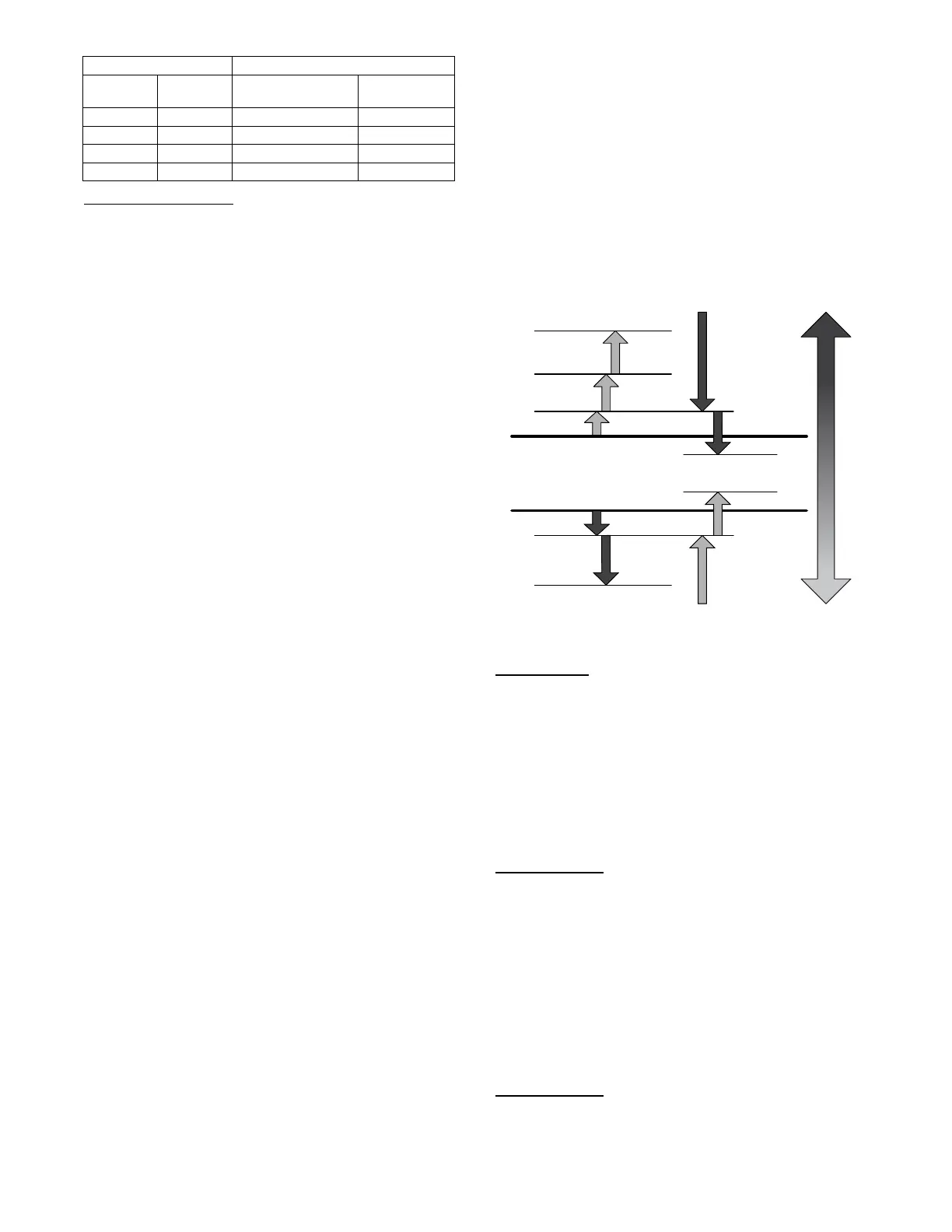
In general the system demand will increase based on the demand
compared to the demand switch states in Fig. 11. The demand
cannot increase until Time guard 1 (DEMAND TIMEGUARD1)
expires. The LCON and LHON thresholds will also cau se the
system demand to be reduced. When the demand hits the off switch
stages the system demand will be set to NO DEMAND. These
switch stages are in the SETTINGSSET POINTS
TEMP
DEMAND CONFIG submenu.
The cooling and heating demand level up configurations (COOL
DMD LEVEL UP and HEAT DMD LEVEL UP) will restrict a
system demand increase if the demand trend is less than the level
up configuration. These level up configurations will also increase
the system demand if the demand trend is greater than it for greater
than the Time guard 2 (DEMAND TIMEGUARD2).
The system demand will increase if it has remained at the same
state for greater than Time Guard 3 (DEMAND TIMEGUARD3).
Cool Setpoint
Heat Setpoint
LCON
LHON
MCON
HCON
HHON
LHOF
LCOF
Decrease
Demand
Decrease
Demand
SPACE TEMP
C14323
Fig. 11 -- Space Sensor System Demand Switch States
RAT Demand
When the unit control type is configured for return air sensor
(UNIT CONTROL TYPE = RAT SEN) the level 5 demand in
Table 8 will be determined the same as space sensor but using the
return air temperature (RETURN AIR TEMP) instead of the space
temperature (SPACE TEMPERATURE).
Occupancy Determination
The building’s occupancy is affected by a number of different
factors. Occupancy affects the unit set points and the operation of
the economizer. The factors affecting occupancy are listed below
from highest to lowest priority.
Level 1 Priority
Level 1 classification is a force/write to occupancy and can occur
two ways. Listed in order of priority: force on OCCUPIED, and a
Linkage write. The CCN point OCCUPIED is forced via an
external device such as a ComfortIDt controller or a service tool:
when OCCUPIED is forced to YES, the unit is considered
occupied, when OCCUPIED is forced to NO, the unit is
considered unoccupied. If the unit is being controlled by Linkage,
the occupancy is communicated and mapped to OCCUPIED as an
input. Linkage does not force the point only write to it, therefore a
force applied to OCCUPIED will override it.
If OCCUPIED is not being forced or written to, proceed to the
level 2 priority.
Level 2 Priority
Level 2 is considered occupant interaction, and consists of Timed
Override and Remote Occupancy Switch. A timed override button
press will override a remote occupancy switch if both are installed
for operation.
 Loading...