27
IAQ (Analog Input)
When IAQ assigned channel (IAQ SENSOR CHAN) is set for an
analog input that input channel will be mapped to the Indoor Air
Quality (IAQ LEVEL). The control is configured for indoor air
quality sensors which provide 4 to 20 mA signal for 0 to 2000 ppm
CO
2
. If the sensor being used has a different range, the ppm
display range must be reconfigured by entering new values for the
IAQ Sensor Value at 4mA (IAQ PPM @ 4MA) and IAQ Sensor
Value at 20mA (IAQ PPM @ 20MA).
ANALOG IAQ CTRL =0(NoIAQ)
This signifies that there is no IAQ sensor installed. The economizer
damper will operate based on the minimum position curve.
ANALOG IAQ CTRL = 1 (DCV)
During Demand Controlled Ventilation (DCV), the damper
modulates on or between two ventilation curves depending upon
the difference between the Indoor Air Quality (IAQ LEVEL) and
the Outdoor Air Quality (OAQ LEVEL). The lower of these two
curves is referred to as the IAQ Minimum Position Curve, and the
higher curve is the Minimum Position curve discussed in the
Minimum Ventilation section under Economizer Operation. Refer
to that section on how the minimum Position curve is created. See
Example Curves in Fig 19.
The IAQ Minimum Position curve is created by applying the
difference of the IAQ position at maximum fan speed (IAQ POS @
MAX SP D) and the Economizer minimum at maximum fan speed
(MIN POS @ MAX FAN) in relationship to the minimum position
curve. The IAQ position at maximum fan speed (IAQ POS @
MAX SP D) should be set to an economizer position that brings in
enough fresh air to remove contaminates and CO
2
generated by
sources other than people. The Economizer minimum at maximum
fan speed (MIN POS @ MAX FAN) should be set to an
economizer position that brings in fresh air to remove contaminates
and CO
2
generated by all sources including people when the
indoor fan is operating at the IDF Maximum Fan Speed
(MAXIMUM IDF SPEED). The Economizer minimum at
maximum fan speed (MIN POS @ MAX FAN) value is the design
value for maximum occupancy.
The economizer Min Position in Effect (EFFECTIVE MIN POS)
will follow the IAQ Minimum Position curve while the Indoor Air
Quality level (IAQ LEVEL) is less than the Outdoor Air Quality
Level (OAQ LEVEL). The control will begin to open the damper
more than the IAQ Minimum Position curve when the IAQ level
begins to exceed the OAQ level by a configurable amount. This
amount is referred to as AQ Differential Low (LOW AIR.Q
DIFF). When the differential between IAQ and OAQ reaches AQ
Differential High (HIGH AIR.Q DIFF), the economizer Min
Position in Effect (EFFECTIVE MIN POS) will follow the
Minimum Position Curve. When the IAQ/OAQ differential is
between AQ Differential Low (LOW AIR.Q DIFF) and AQ
Differential High (HIGH AIR.Q DIFF), the control will modulate
the damper between the IAQ Minimum Position Curve and the
Minimum Position Curve in a linear manner as shown as the
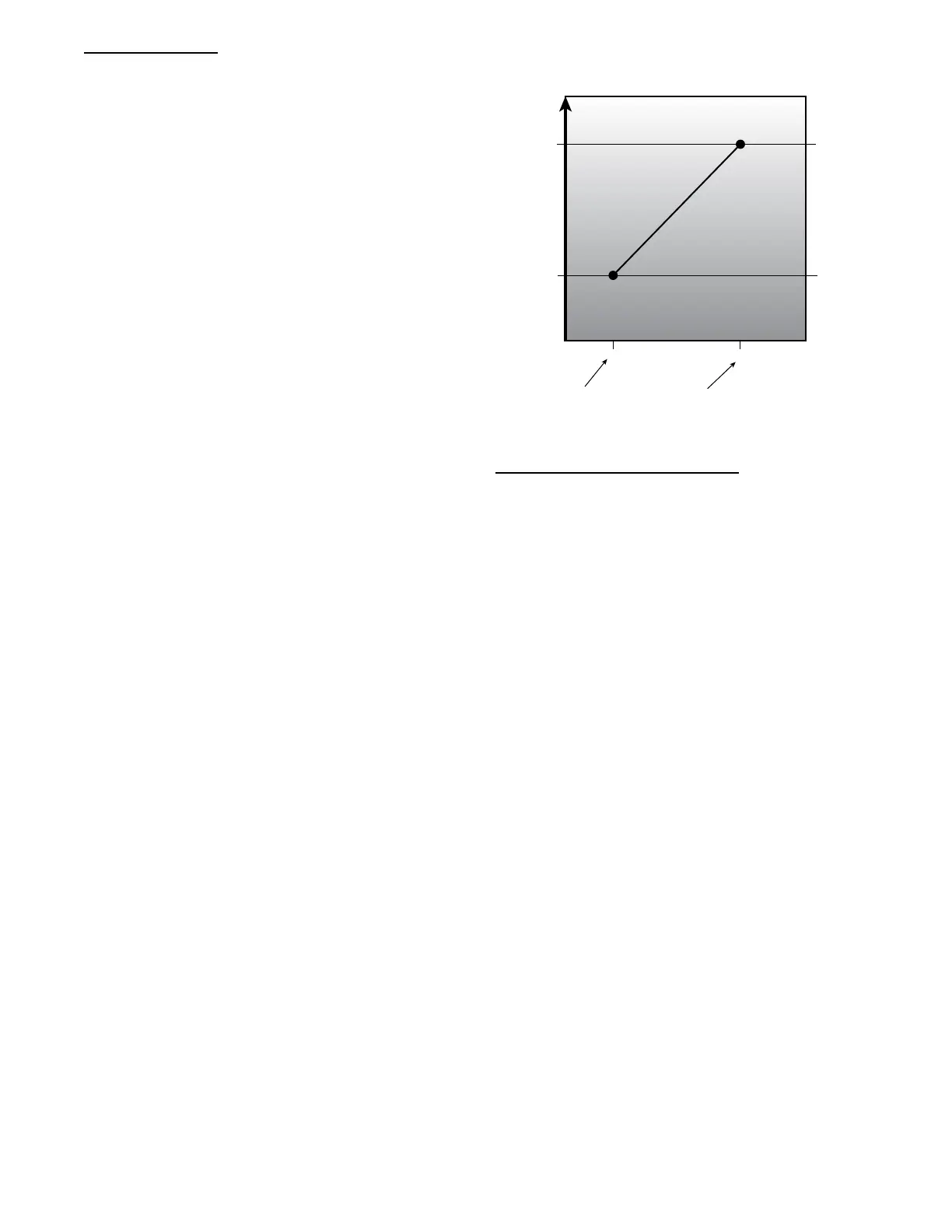
shaded area in Fig. 19. As a simple example Fig. 21 shows the Min
Position in Effect (EFFECTIVE MIN POS) relationship while the
Commanded Fan Speed (ECON CMD POSITION) is held at the
maximum speed.
ANALOG IAQ CTRL = 2 (Override IAQ)
Override IAQ is reserved for a future release.
ANALOG IAQ CTRL = 3 (Control Minimum Position)
An external 4 to 20 mA source is used to set the Min Position in
Effect (EFFECTIVE MIN POS). The 4mA signal corresponds to
0% and the 20 mA signal corresponds to 100%. In this mode,
configuration such as Economizer minimum at maximum fan
speed (MIN POS @ MAX FAN), IAQ position at maximum fan
speed (IAQ POS @ MAX SPD) and the economizer minimum
position and DCV minimum position curves in Fig. 19 and Fig. 21
are not used. If the indoor fan is not operating, the economizer
position will be zero. The actual damper position may exceed the
economizer Min Position in Effect (EFFECTIVE MIN POS) to
provide economizer cooling.
VENTILATION FOR PEOPLE
VENTILATION FOR SOURCES
INCREASING VENTILATION
MIN POS @
MAX FAN
IAQ POS @
MAX FAN
100 700 INSIDE/OUTSIDE CO
2
DIFFERENTIAL
LOW AIR.Q DIFF HIGH AIR.Q FIFF
C14328
Fig. 21 -- Example
Outdoor Air Quality (Analog Input)
The default for the Outdoor Air Quality (OAQ LEVEL) is 400
ppm CO
2
when the OAQ sensor is not assigned an input channel.
When OAQ Assigned channel (OAQ SENSOR CHAN) is set for
an analog input that input channel will be mapped to the Outdoor
Air Quality (OAQ LEVEL). The outdoor air quality sensor
provides a 4 to 20 mA signal corresponding to 0 to 2000 ppm
CO
2
. If a field supplied sensor has a different range, the ppm
display range must be reconfigured by entering new values for the
OAQ Sensor Value at 4mA (OAQ PPM @ 4MA) and OAQ Sensor
Value at 20mA (OAQ PPM @ 20MA).
Pre--occupancy Purge
The control has the option for a pre--occupancy purge to refresh the
air in the space prior to occupancy. This feature is enabled by
setting PREOCC PURGE ENBL to Yes. This function is also
referred to as the IAQ purge function.
The IAQ Purge will operate under the following conditions:
S Purge is enabled
S the unit is in the unoccupied state
S Current Time is valid
S Next Occupied Time is valid
S time is one hour prior to next occupied period
S the OAT is greater than the lockout (PREOCC LOW LIMIT)
The IAQ Purge Position curve is created by applying the difference
of the IAQ purge position at maximum fan speed (PURGE POS @
MAX) and the Economizer minimum at maximum fan speed (MIN
POS @ MAX FAN) in relationship to the minimum position curve.
The IAQ purge position at maximum fan speed (PURGE POS @
MAX) should be set to an economizer position that brings in
enough fresh air over an hour period to remove contaminates and
CO
2
during the unoccupied period. When the preoccupancy purge
function is active (IN PREOCC PURGE?), the economizer Min
Position in Effect (EFFECTIVE MIN POS) will follow the IAQ
Purge Position curve.
Temperature Compensated Start
Space control set points are usually set to 2 different levels for
unoccupied period and occupied period. Unoccupied set points
saves energy, while occupied set points provide occupant comfort.
The time period it takes for the RTU to bring the space from its
current condition in unoccupied mode to its occupied set point is
 Loading...