22
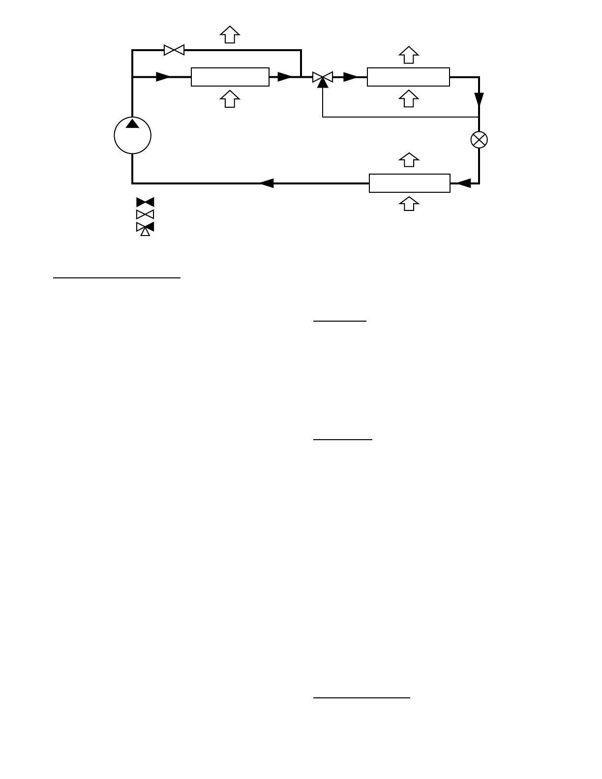
HUMIDI-MIZER COIL
COMPRESSOR
OUTDOOR AIR
INDOOR SUPPLY
AIR
INDOOR RETURN
AIR
3-WAY
VALVE
RDV
VALVE
EVAPORATOR COIL
CONDENSER COIL
= CLOSED VALVE
= OPEN VALVE
= 3-WAY VALVE
EXPANSION
VALVE
(TXV)
C14116
Fig. 18 -- Hot Gas Reheat Mode – Humidi--MiZer System 48/50LC 07-- 26
Reheat Mode Diagnostic Help
The status of reheat mode sensor inputs may be viewed within the
display INPUTS menu. The status of reheat mode outputs may be
viewed within the display OUTPUTS or RUN STATUSMODE
menu. Additional diagnostic help, including status of circuit reheat
temperature limit lockouts may be viewed within the
Humidi--MiZer sub--menu of the cooling mode diagnostic table at
RUN STATUSCOOLDEHUM. The Service Test mode may
be used to force the system to operate Dehumidification mode (Hot
Gas Reheat) and Dehum/Mech Cooling mode (Subcooling), or to
independently operate the reheat valve control outputs.
The following forced operating states are available service test
operations for a Humidi--MiZer system equipped unit:
SER VI CE TEST COOL TEST HUMIDIMIZER TEST
LEVEL
A value of “0” sets reheat control test to “Off.”
SER VI CE TEST COOL TEST HUMIDIMIZER TEST
LEVEL
A value of “1” sets Humidi--MiZer control test to “Dehum/Mech
Cooling mode (Subc ool ing).”
SER VI CE TEST COOL TEST HUMIDIMIZER TEST
LEVEL
A value of “2” sets Humidi--MiZer test to “Dehumidification mode
(Hot Gas Reheat).”
SER VI CE TEST INDEPENDENTS LIQ DIVERT A TEST
A val ue of “On” wil l turn on the 3--Way Li qui d Di verter Valve
(LDV) .
SER VI CE TEST INDEPENDENTS REHEAT A TEST
A value of “ O n” will tur n on the Reheat Dis charge Valve (RDV ).
Indoor Fan Based Dehumidification
Belt Drive units that are not factory configured for Humidi-- Mizer
operation can be set for improved dehumidification operation
through fan based humidification (FBD), SETTINGS
UNIT
CONFIGURATIONS
COOLING
FBD TYPE. Units are
factory defaulted to FBD TYPE = 0 which means that any dehum
demand is ignored. There are two fan based dehumidification
options, Max Comfort (FBD TYPE = 1)andMax
Dehumidification (FBD TYPE = 2). Fan based dehumidification
requires the installation and configuration of either a space relative
humidity sensor or a relative humidity switch input. The Space
Humidity Switch configuration, SETTINGS
UNIT
CONFIGURATIONS
SWITCH INPUTS CONFIGS
HUMSTAT CHANNEL identifies the normally open or normally
closed status of this input at HIGH humidity. The RH Sensor
configuration, SETTINGS
UNIT CONFIGURATIONS
ANALOG INPUTS CONFIGS
SPRH SENSOR CHANNEL,
identifies the point on the MBB (Main Base board) or the IOB
(Input Output board) the sensor was wired into.
Max Dehum
Whe n the FBD Type is set to (2) Max Dehum , the cont rol will try to
satisfy the dehumidification demand. When the unit receives a dehum
dem and a PID cont rol algorithm will modulate the indoor fan while
the com pr ess or is runni ng to maintain mi nimum suction temperature
(FBD H_SST). Wit h a Y1 a nd dehum dema nd, the unit will run the
com pr ess or unloaded (48/50LC04--06) or will run the A1 compressor
only (48/50LC07--26). W ith a Y2 a nd dehum de m and, the unit will
run wit h the com pr ess or at ful l load (48/ 50LC04--06) or will run wit h
the A2 compr essor only (48/ 50LC07--26). W ith a Y3 and dehum
dem and (48/50LC07--26 only), the unit will run both compressors.
Max Comfort
When the FBD Type is set to (1) Max Comfort, the control will try
to satisfy the dehumidification demand and minimize cold air
dump. When the unit receives a dehum demand a PID control
algorithm will modulate the indoor fan while the compressor is
running to maintain the minimum FBD supply air comfort set
point (FBDH_SAT) while also maintaining the minimum suction
temperature (FBDH_SST). With a Y1 and dehum demand, the unit
will run the compressor unloaded (48/50LC04--06) or will run the
A1 compressor only (48/50LC07--26). With a Y2 and dehum
demand, the unit will run with the compressor at full load
(48/50LC04-- 06) or will run with the A2 compressor only
(48/50LC07-- 26). With a Y3 and dehum demand (48/50LC07--26
only), the unit will run both compressors.
Heating Operation
The 48/50LC unit’s heating operation consists of: demand and
mode determination, staging request to satisfy the demand, and
handling a request with the unit’s resources. These resources can be
gas heat or electric heat. This section covers both gas heat units and
electric heat units. The Type of Heat Installed (UNIT TYPE OF
HEAT) configuration will be factory set to 1 for gas units and 0 for
electric heat units. The unit enters a heating mode based on a
demand, decides how to satisfy the demand, executes its plan, and
then leaves the heating mode.
Heating M ode Control
The heating HVAC mode (OPERATING MODE) has 3 different
operating sub modes (SUBMODE): HEATING, HEATING
PREVENTED, and SHUTTING HEAT OFF. These are all part of
a general heating mode and resemble the action heat mode is taking
 Loading...