4 - MANAGING A NETWORK OF CONTROLLERS AND HMI TERMINALS
To establish communication between controllers and terminals,
it is necessary to give an address to each of the elements.
This addressing is performed at the factory, but if a defective
component is replaced (controller or terminal), it may have to be
performed on site.
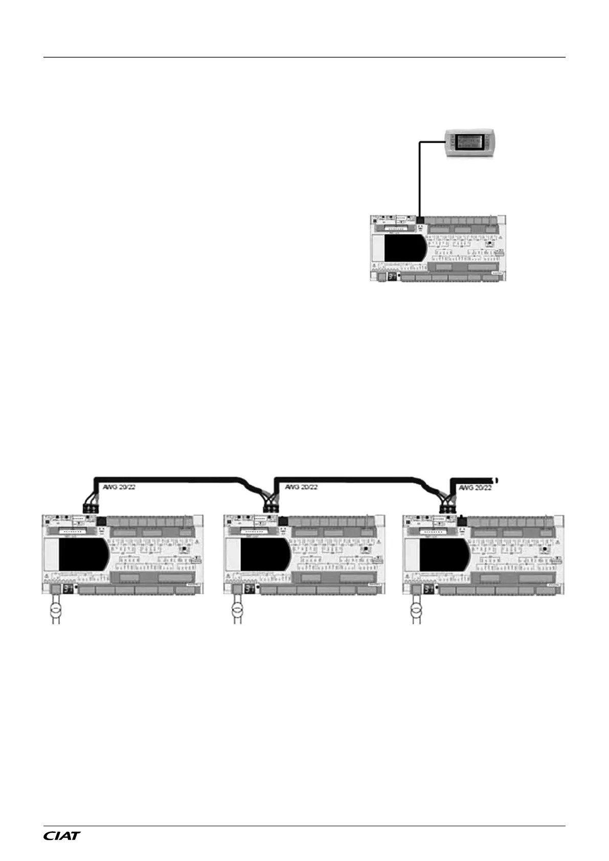
4.1 - One controller and one terminal:
The terminal addressing procedure is described in the following
section, paragraph 5.4.3. The procedure for the controller is in
paragraph 5.4.3. The controller and terminal must have dierent
addresses. The example opposite shows one addressing option
Terminal address: 32
Controller address: 01
P01 : Adr Priv/Shared
Trm1 : 32 Pr
Trm2 : None Sh
Trm3 : None --OK?
4.2 - Several controllers and terminals:
Several terminals or controllers may be interconnected, without any additional components, using the pLAN (local area network).
This enables several terminals to be used to display the parameters from one controller or, conversely, one terminal can be used
to display the parameters from several controllers.
Only the electrical connection and conguration of the addresses need to be performed by the user.
4.3 - Electrical connections for the pLAN (local area network)
4.3.1 - Connecting controllers to the pLAN
The electrical connection between the controllers in the pLAN (RS485) is installed using an AWG20/22 shielded cable composed
of a twisted pair and a shield. The cards must be connected in parallel using the J14 connector.
The rst and last controller must be no more than 500m apart.
EN-27 FLOWAY ACCESS
 Loading...