interface.
EIA/TIA-232
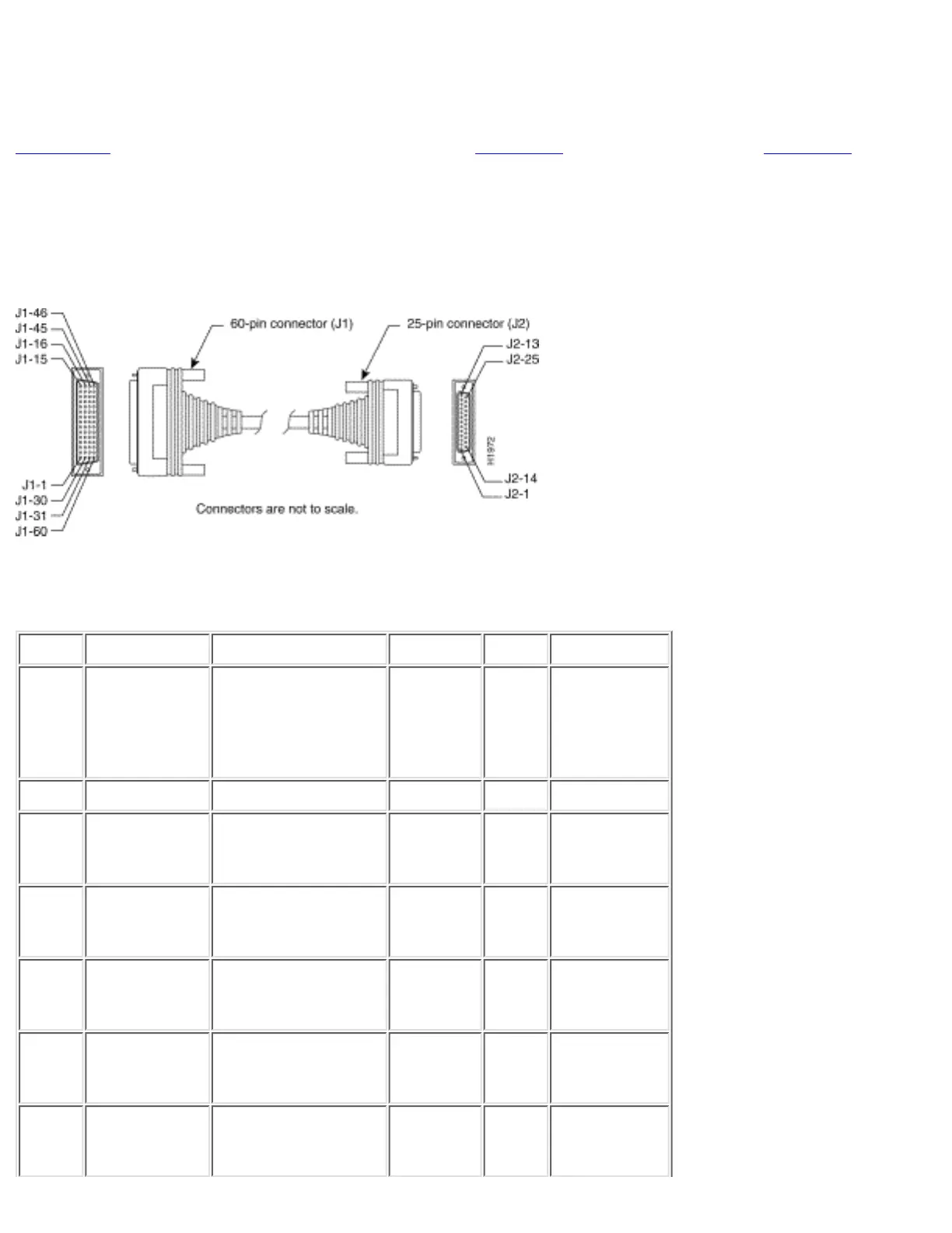
Figure C-7 shows the EIA/TIA-232 cable assembly. Table C-7 lists the DTE pinouts. Table C-8 lists the
DCE pinouts. Arrows indicate signal direction: --> indicates DTE to DCE, and <-- indicates DCE to
DTE.
Figure C-7: EIA/TIA-232 Cable Assembly
Table C-7: EIA/TIA-232 DTE Cable Pinouts (DB-60 to DB-25)
(Continued)
60 Pin Signal Description Direction 25 Pin Signal
J1-50
J1-51
J1-52
MODE_0
GND
MODE_DCE
Shorting group - - -
J1-46 Shield GND Single - J2-1 Shield GND
J1-41
Shield
TxD/RxD
-
Twisted pair no. 5 -->
-
J2-2
Shield
TxD
-
J1-36
Shield
RxD/TxD
-
Twisted pair no. 9 <--
-
J2-3
Shield
RxD
-
J1-42
Shield
RTS/CTS
-
Twisted pair no. 4 -->
-
J2-4
Shield
RTS
-
J1-35
Shield
CTS/RTS
-
Twisted pair no. 10 <--
-
J2-5
Shield
CTS
-
J1-34
Shield
DSR/DTR
-
Twisted pair no. 11 <--
-
J2-6
Shield
DSR
-
http://www.cisco.com/univercd/cc/td/doc/product/access/acs_fix/cis2500/2520/2520_23/c2520cab.htm (8 of 17) [10/27/2000 3:08:10 PM]
 Loading...