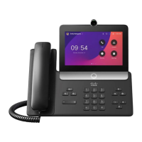
This diagram shows the spine connector.
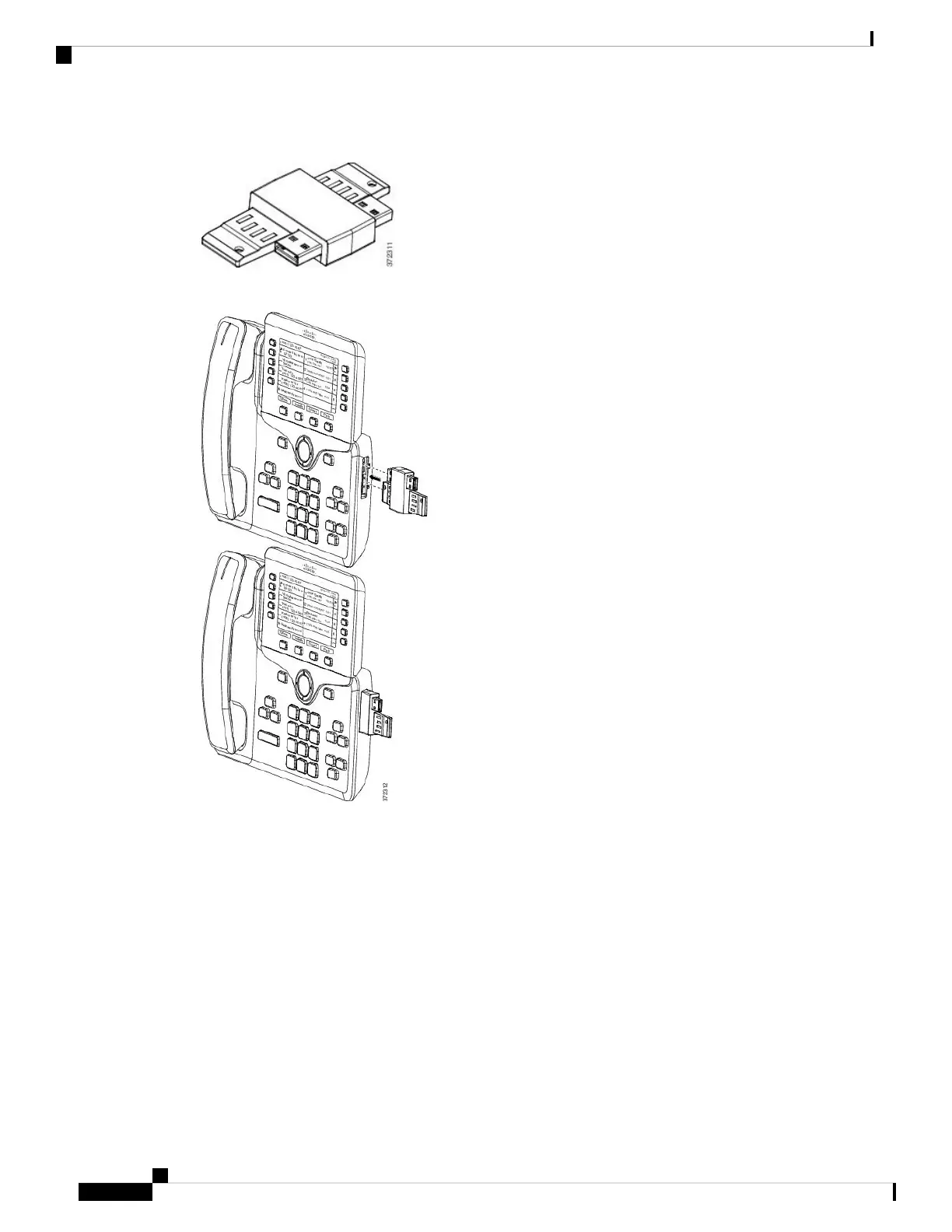
This diagram shows the installation of the spine connector.
Step 7 Connect the other end of the spine connector to the key expansion module as shown in this diagram.
a) Align the spine connector with the key expansion module accessory connector ports.
b) Firmly press the key expansion module into the spine connector.
The first key expansion module is now connected to the Cisco IP Phone.
Step 8 Use a second key expansion module spine connector to connect the second key expansion module to the first
key expansion module.
Step 9 Use a third key expansion module spine connector to connect the third key expansion module to the second
(middle) key expansion module. This figure shows a Cisco IP Phone with three key expansion modules
attached.
Cisco IP Phone 8800 Series Multiplatform Phones Administration Guide
116
Hardware and Accessory Installation
Connect Two or Three Key Expansion Modules to a Cisco IP Phone
 Loading...