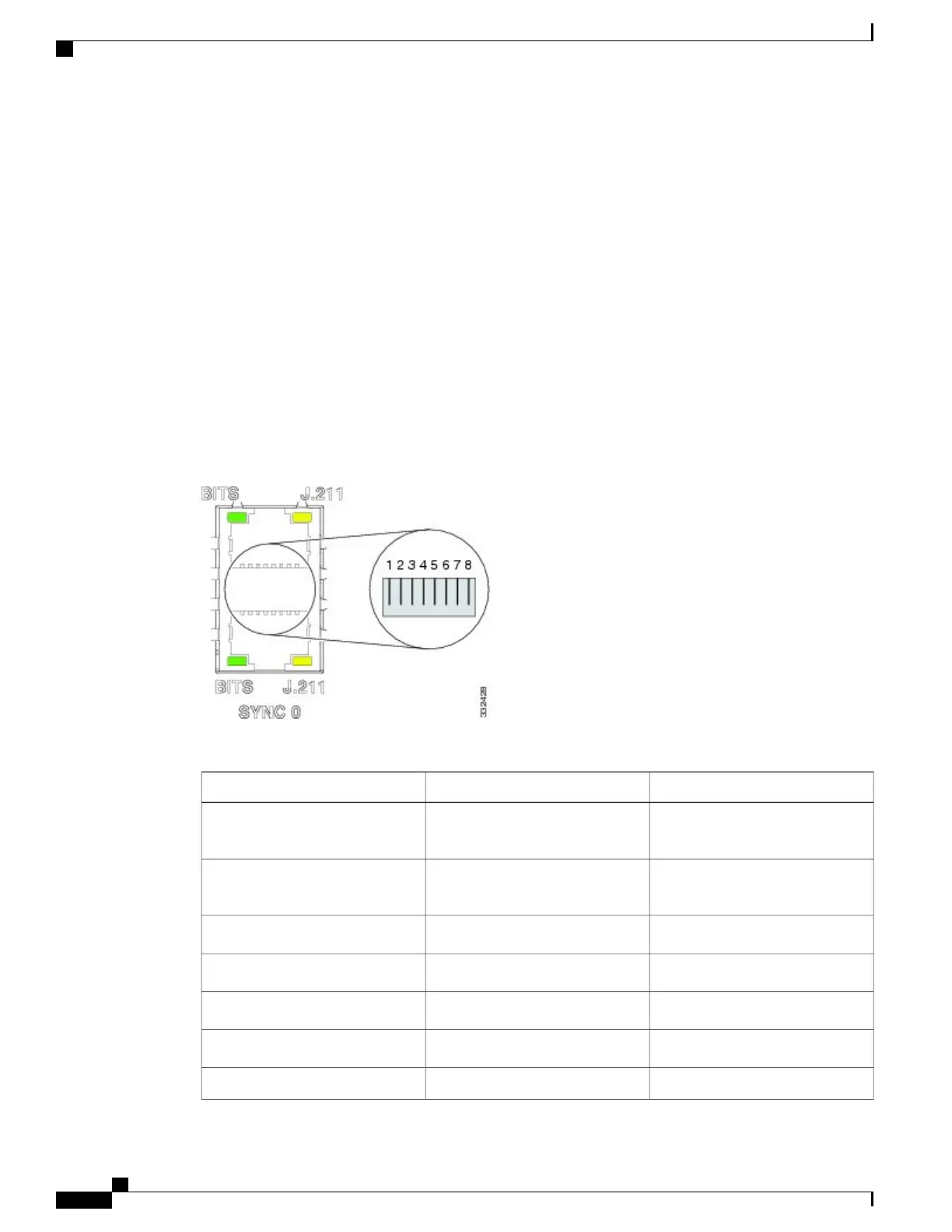
SYNC Port LED Indicators
The SYNC port connector has integral LED indicators (see the following figure). When lit, these LEDs
indicate:
•
in BITS mode:
◦ Green — Connection is alive.
◦ Amber — A fault has occurred.
•
in J.211 mode:
◦ Green — DTI is operating in normal mode.
◦ Amber — DTI is operating in fast mode.
Figure 27: SYNC Port Connector
Table 7: BITS/J.211 Connector Pinout
NoteSignalPin
Bi-direction for DTI, T1/E1/64K
Input
DTI_P/BITS_RX_P1
Bi-direction for DTI, T1/E1/64K
Input
DTI_P/BITS_RX_N2
——
3
T1/E1/6.321M OutputBITS_TX_P*4
T1/E1/6.321M OutputBITS_TX_N*5
——
6
——
7
Cisco ASR 9001 and Cisco ASR 9001-S Routers Hardware Installation Guide
30
Preparing for Installation
Sync Ports Connection Guidelines

 Loading...


