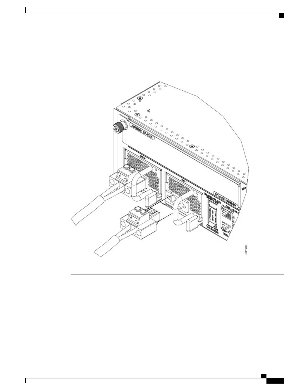
To prevent injury and damage to the equipment, always attach the ground and source DC power
cable to power module terminals in the following order: (1) ground to ground, (2) positive (+) to
positive (+), (3) negative (–) to negative (–).
Caution
Figure 56: Typical Power Connections for a Single DC Power Module
Step 4
Proceed to the next section.
Powering on the Router
Follow these steps to turn on power to either an AC-powered or DC-powered router:
Cisco ASR 9001 and Cisco ASR 9001-S Routers Hardware Installation Guide
83
Installing Modules and Cables in the Chassis
Powering on the Router

 Loading...


