Connecting a Cable to the GNSS Antenna Interface
The GNSS module is not hot swappable.Note
Step 1
Connect one end of a shielded coaxial cable to the GNSS RF IN port.
Step 2
Connect the other end of the shielded coaxial cable to the GNSS antenna after the primary protector.
The GNSS RF In port should have a primary protector installed to meet the Local Safety guidelines.Note
•
The GNSS RF In coaxial cable shield must be connected to the Facility Equipment Ground through the chassis.
The chassis must have the ground wire connected to the Facility Equipment Ground.
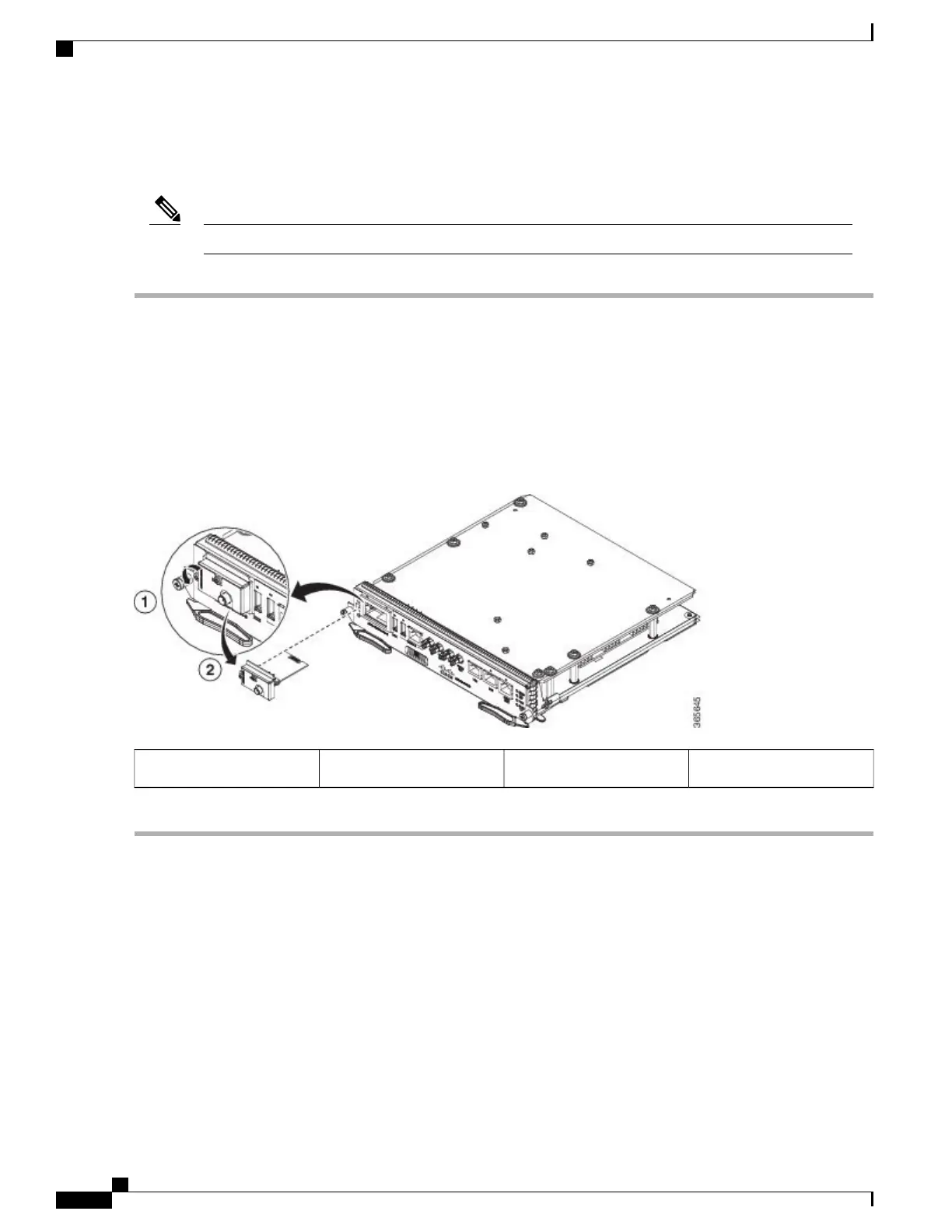
Figure 75: Installing the GNSS Module in the RSP
Inserting the GNSS Module2Screw on the GNSS Module1
Connecting Ethernet Cables
The Cisco ASR 903 Router interface modules support RJ45 or SFP Ethernet ports. For instructions on how
to connect cables to Ethernet SFP ports, see Connecting Cables to SFP Modules.
The RJ45 port supports standard straight-through and crossover Category 5 unshielded twisted-pair (UTP)
cables. Cisco Systems does not supply Category 5 UTP cables; these cables are available commercially.
Cisco ASR 903 Aggregation Services Router Hardware Installation Guide
128
Installing the Cisco ASR 903 Router
Connecting a Cable to the GNSS Antenna Interface

 Loading...


