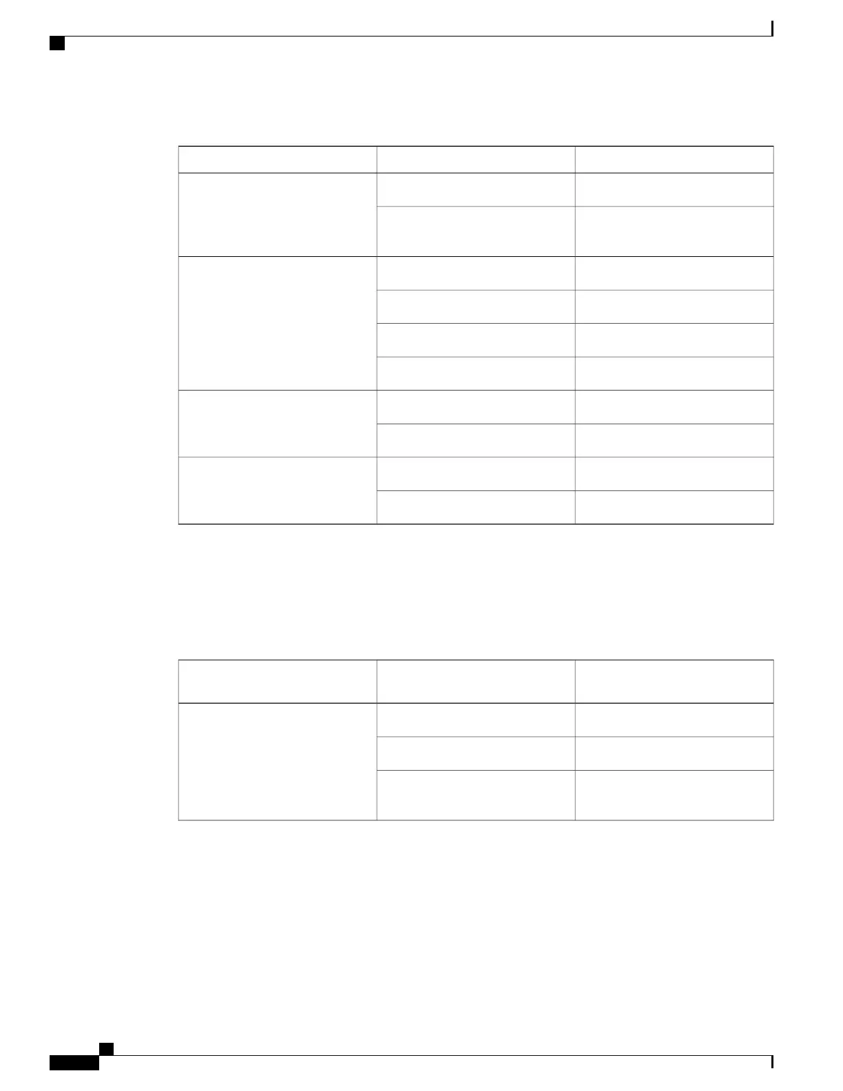
Table 36: Interface Module LEDs
DescriptionColor/StateLED
Disabled/no power to IMOffPower (PWR)
Enabled and power rails on IM in
range
Green
Disabled/power-downOffStatus (STAT)
Failure (on at reset)Red
Booting (if local CPU)Amber
OperationalGreen
SFP receiving good remote signalGreenCarrier/Alarm (C/A)
Remote or local alarm activatedYellow
SFP ready and operating normallyGreenActive/Loopback(A/L)
SFP port in loopback stateYellow
T1/E1 Interface Module LEDs
The table below summarizes the LEDs for the 16-port T1/E1 interface module.
Table 37: 16-port T1/E1 Interface Module LEDs
Description (two LEDs for
eachT1/E1 port)
Color/StateLED
ActiveGreenActive
StandbyBlinking green
Operationally down; card is
disabled or shut down
Off
Cisco ASR 903 Aggregation Services Router Hardware Installation Guide
164
Troubleshooting
Interface Module LEDs

 Loading...


