DescriptionDirectionSignal NamePin
TX RingOutputTX Ring4
TX TipOutputTX Tip5
Not used6
Not used7
Not used8
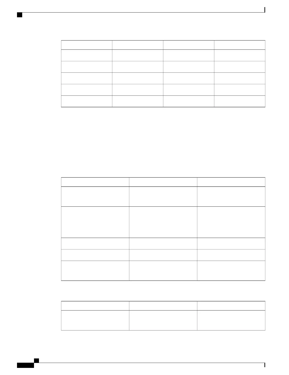
GPS Port Pinout
The platform is capable of receiving or sourcing GPS signals of 1 PPS & 10 MHz. These interfaces are
provided by two mini-coax 50-Ohm, 1.0/2.3 DIN series connector on the front panel. Similarly there are two
mini-coax 50-Ohm connectors provided in the front panel to output this 1PPS and 10MHz.
The table below summarizes the GPS port pinouts.
Table 18: GPS Port Pinout
1PPS (input and output)10 Mhz (input and output)
Input—Rectangular pulse
Output—Rectangular pulse
Input—Sine wave
Output—Square wave
Waveform
Input— > 2.4 volts TTL
compatible
Output— > 2.4 volts TTL
compatible
Input— > 1.7 volt p-p(+8 to +10
dBm)
Output— > 2.4 volts TTL
compatible
Amplitude
50 ohms50 ohmsImpedance
26 microseconds50% duty cyclePulse Width
40 nanoseconds
Input—AC coupled
Output—5 nanoseconds
Rise Time
Table 19: GPS Port Pinout for ASR 900 RSP3
1PPS (input and output)10 Mhz (input and output)
Input—Rectangular pulse
Output—Rectangular pulse
Input—Sine wave
Output—Sine and Square wave
Waveform
Cisco ASR 903 Aggregation Services Router Hardware Installation Guide
146
Troubleshooting
GPS Port Pinout

 Loading...


