Jack PinTelco RXSignal
Name
Board
Pins
Jack PinTelco TXSignal
Name
Board
PIns
Line
428RX_RING_P1657128TX_RING_P1661Line 15
53RX_TIP_P16723TX_TIP_P1611
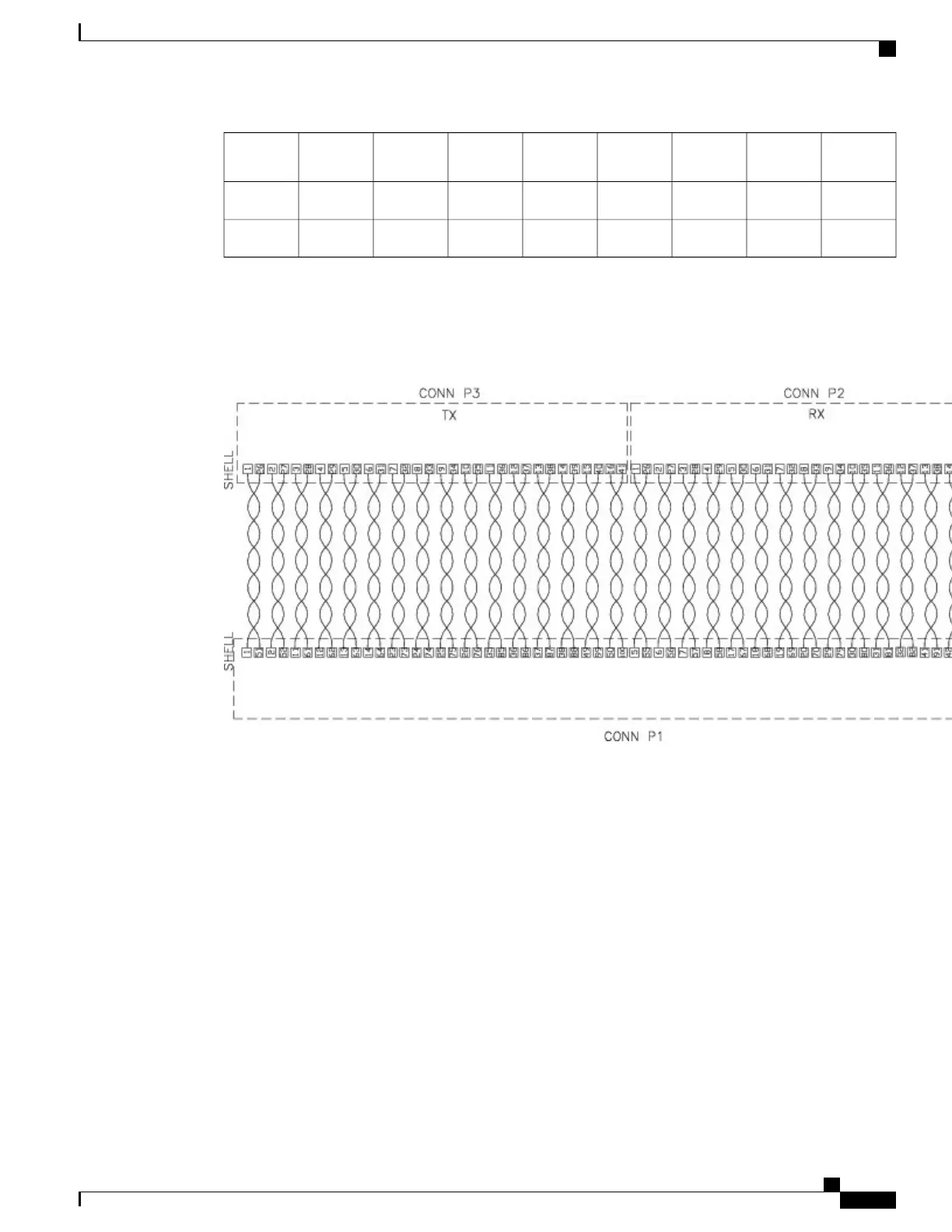
The figure below shows the wiring schematic of the cable used to connect the T1/E1 interface module to the
rear of the patch panel.
Figure 80: Wiring Schematic of Cable between 16 T1/E1 Interface and Patch Panel
32 T1/E1 Interface Module Pinout
The table below summarizes the pinouts of the cable used to connect the 32 T1/E1 interface module to the
rear of the patch panel.
Cisco ASR 903 Aggregation Services Router Hardware Installation Guide
151
Troubleshooting
32 T1/E1 Interface Module Pinout

 Loading...


