32 x T1/E1 Cable Connector
The 32 x T1/E1 interface module requires two patch cables (see Recommended Patch Panel). Each patch
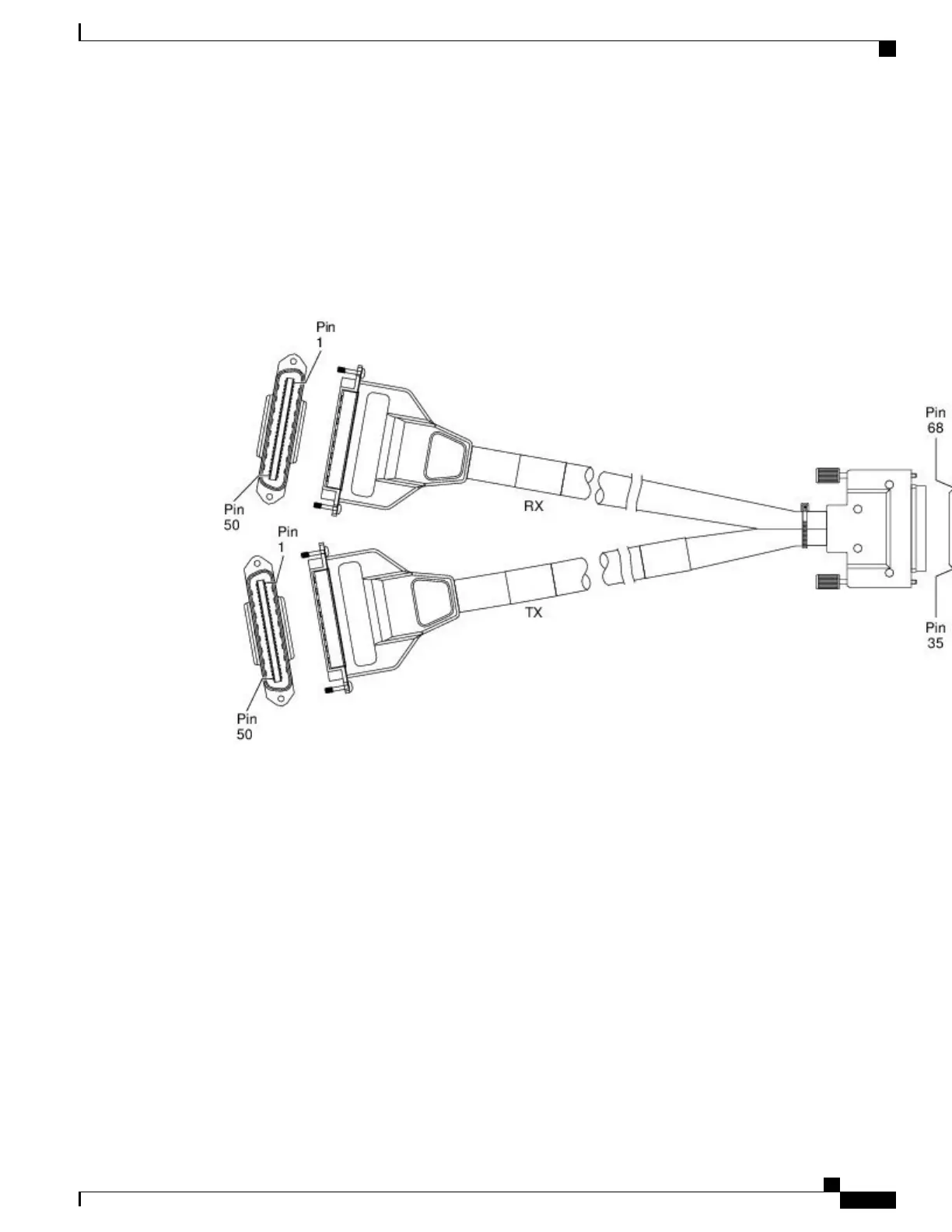
cable (see the figure below ) has a 68-pin connectors that connects with each connector port on the front panel
of the 32 x T1/E1 interface module.
Use the thumbscrews on either side of the connectors to secure the cable to the interface.
Figure 78: 32 x T1/E1 Cable Connector
The other end of the cable has two 50-pin Telco connectors that attach to the rear of a 24-port RJ45 patch
panel. Both connectors are identical: one is for Transmit (TX) and the other is for Receive (RX).
Cisco ASR 903 Aggregation Services Router Hardware Installation Guide
131
Installing the Cisco ASR 903 Router
Connecting T1/E1 cables

 Loading...


