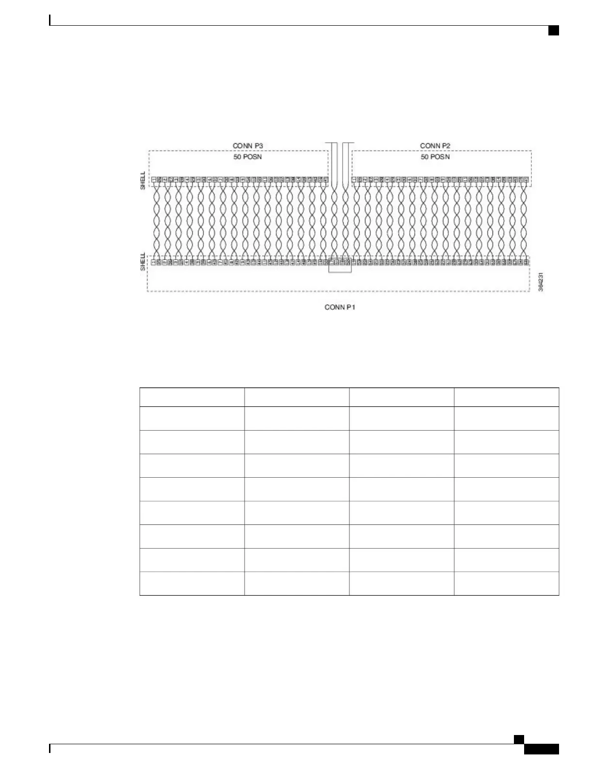
The table below shows the wiring schematic of the cable used to connect the 32 T1/E1 interface module to
the rear of the patch panel.
Figure 81: 32 T1/E1 Wiring Schematic of Cable between 32 T1/E1 Interface and Patch Panel
8 T1/E1 Interface Module RJ48C Port Pinnouts
Table 26: RJ48C Connector Pin-out for 8 T/E1 Interface Module
DescriptionDirectionSignalPin
Receive TipInputRX_TIP1
Receive RingOutputRX_RING2
Not Connected3
Receive TipInputTX_TIP4
Receive RingOutputTX_RING5
Not Connected6
Not Connected7
Not Connected8
Serial Cable Pinouts
The following sections summarize the pinouts for 14-port serial interface module when used with the cable
types specified in Connecting Serial Cables.
Cisco ASR 903 Aggregation Services Router Hardware Installation Guide
155
Troubleshooting
8 T1/E1 Interface Module RJ48C Port Pinnouts

 Loading...


